
Communication method, communication system, access control apparatus, and computer readable storage medium

a communication system and access control technology, applied in the direction of testing/monitoring control systems, near-field systems using receivers, instruments, etc., can solve the problems of increasing the probability of failing to access, and disadvantageously deteriorating efficiency

Inactive Publication Date: 2008-04-24
FUJITSU LTD
View PDF3 Cites 1 Cited by
  • Summary
  • Abstract
  • Description
  • Claims
  • Application Information

AI Technical Summary

Benefits of technology

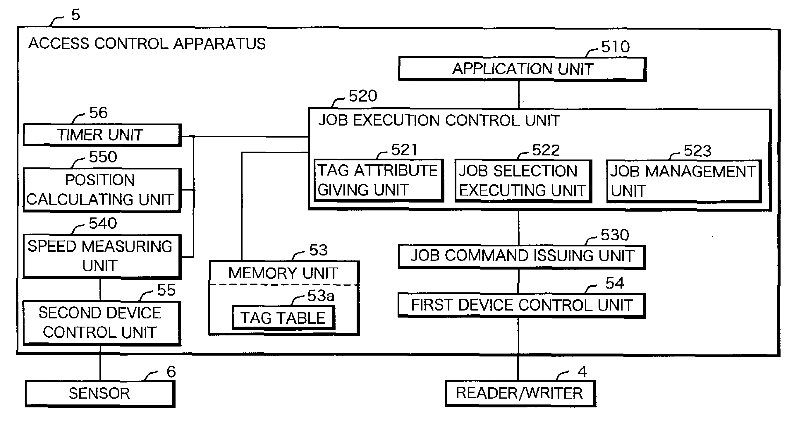
[0011]In order to achieve the above objects, straightforwardly, the following configuration is employed. That is, for example, an elapsed time from antenna switching time measured at time of the first access trial for collecting identification information of an IC tag to time when the collection is succeeded is associated with the collected identification information as time information, and, for example, identification information is selected on the basis of the time information at the second access for reading or writing information from / on IC tags to make it possible to access the respective IC tags at optimum times, respectively.
[0012]The present invention employs the following configuration. Positions of antennas which gain the first access with respect to moving directions of IC tags are associated with the identification information as position information, and identification information is selected on the basis of the position information at the second access to make it possible to start out access to the IC tags from an antenna which is expected to easily access the IC tags based on the position information.
[0026]With the above configuration, in the present invention, since an IC tag which can be most expectedly accessed at the time of access trial can be selected, respective IC tags can be accessed at optimum times, respectively. Therefore, failure of access can be decreased, and overall efficiency including shortening of time for accessing the IC tags can be improved.
[0028]With the above configuration, in the present invention, since an IC tag which is accessed at the same position with respect to the moving directions of the IC tags can be selected, when an easily accessible antenna arranged at a position having actual achievement of access to the IC tags, for example, the first antenna is arranged on the right of the moving directions of the IC tags, access can be started from the second antenna arranged on the right like the first antenna. Therefore, failure of access is prevented, and overall efficient including shortening of time for accessing the IC tags can be improved.
[0029]Furthermore, according to the present invention as described above, identification information is selected on the basis of position information and time information to make it possible to start access to an IC tag from an optimum antenna at optimum time. Therefore, failure of access is prevented, and overall efficiency including shortening of time for accessing IC tags can be improved.

Problems solved by technology

In this case, when the IC tags move at a high speed, the probability of failing to access increases.
In contrast to this, when the moving speed is lowered, the failure of access is eliminated, but overall efficiency is disadvantageously deteriorated.
However, as described above, even though the plurality of antennas are arranged, when a moving speed of the IC tags increases, or when the number of IC tags increases, the probability of failing to access increases as a matter of course.
For example, in situations that the system tries to access an IC tag outside cover areas of the antennas or just passing through the cover areas, the system cannot normally access the IC tag.

Method used


Image

  • Communication method, communication system, access control apparatus, and computer readable storage medium
  • Communication method, communication system, access control apparatus, and computer readable storage medium
  • Communication method, communication system, access control apparatus, and computer readable storage medium

Examples


Embodiment Construction

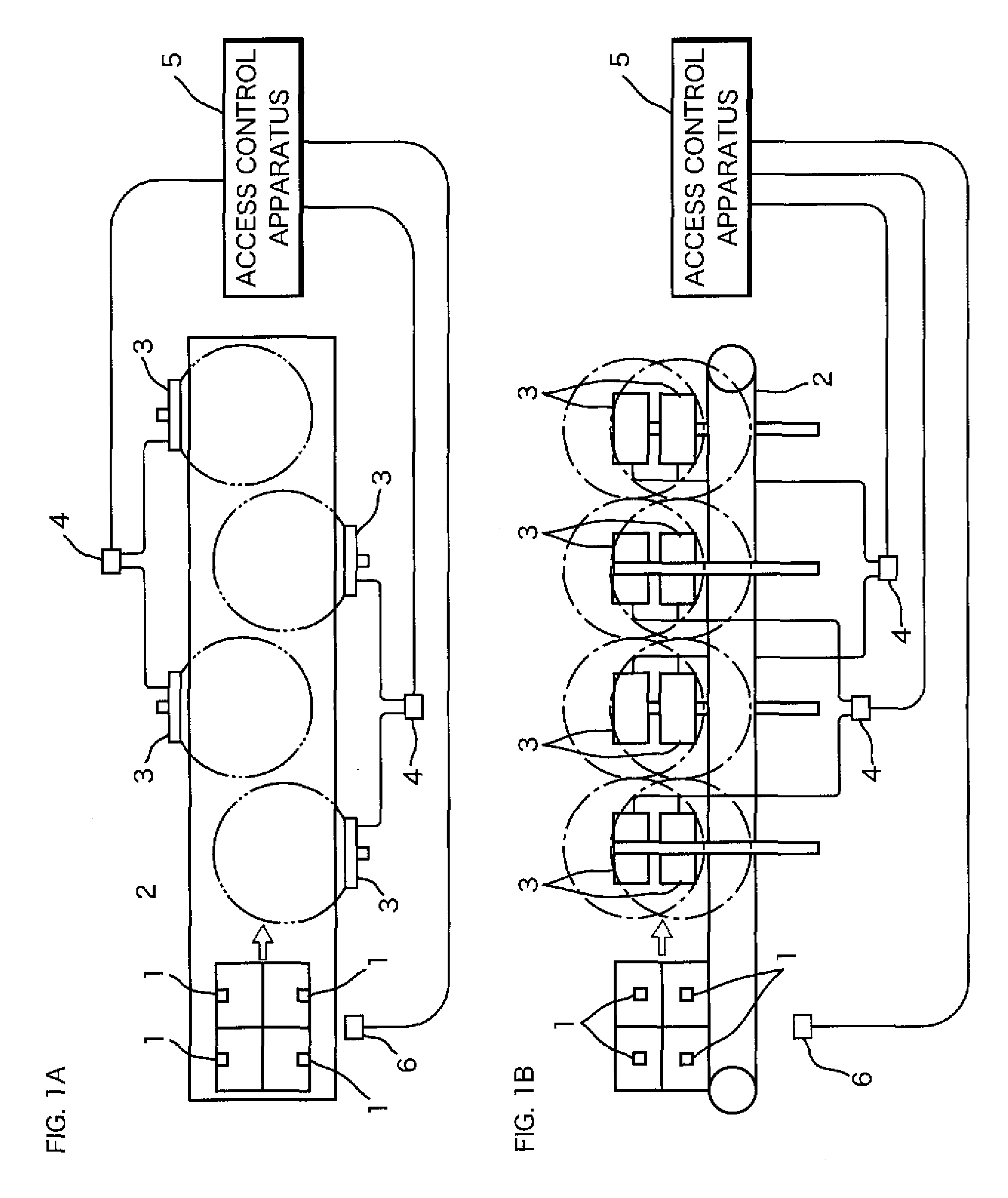
[0038]The present invention will be described below in detail with reference to the accompanying drawings. FIG. 1A and FIG. 1B are conceptual diagrams showing a configuration of a communication system according to the present invention. FIG. 1A is a plan view of a communication system according to the present invention when viewed from above, and FIG. 1B is a side view of the communication system. In FIG. 1A and FIG. 1B, reference numeral 1 denotes a passive IC tag (RFID tag). The IC tags 1 are stuck on articles such as parts, products, and storage boxes respectively, and conveyed by a conveying device 2 such as a belt conveyer in a direction indicated by an arrow in FIG. 1A and FIG. 1B. This direction is called a moving direction.

[0039]Along a moving path of the IC tags 1 conveyed by the conveying device 2, a plurality of antennas 3 are arranged. In the example shown in FIG. 1A and FIG. 1B, antenna tables each having the two antennas 3 installed on upper and lower sides are alterna...


PUM


Abstract

Identification information for identifying IC tags are recorded in association with time information expressing time (timing) at which access using a first antenna is gained, for example, time from when antennas are switched to when the access is gained and position information representing positions of the antenna with respect to a moving direction of the IC tags, identification information is selected on the basis of time for switching to a second antenna arranged on a downstream side of a first antenna, the recorded time information, a position of the second antenna, and the recorded position information, and the IC tags are accessed by using the second antenna on the basis of the selected identification information. When the IC tags are accessed by the plurality of antennas arranged along the moving path of the IC tags, failure of access can be prevented, and overall efficiency can be improved.

Description

CROSS-REFERENCE TO RELATED APPLICATIONS[0001]This Nonprovisional application claims priority under 35 U.S.C. §119(a) to Japanese Patent Application No. 2006-287883 filed in Japan on Oct. 23, 2006, the entire contents of which are hereby incorporated by reference.BACKGROUND[0002]1. Field of the Invention[0003]The present invention relates to a communication method of accessing each of a plurality of IC tags two or more times by using a plurality of antennas arranged along a moving path of an IC tag, a communication system to which the communication method is applied, an access control apparatus used in the communication system, and a computer program product to realize the access control apparatus. In particular, the present invention relates to a communication method, a communication system, an access control apparatus, and a computer program product which make it possible to efficiently access a large number of IC tags moving at a high speed.[0004]2. Description of Related Art[0005...

Claims


Application Information

Patent Timeline
IPC IPC(8): G08B13/14G05B23/02
CPCG06K7/10079G06K7/10316G06K7/10445G06K7/10356G06K7/10346G06K17/00H04B7/24H04B5/48
Inventor SUGANO, HIROYASUMATSUI, KAZUKIKIHARA, HIDETOMATSUDA, MASAHIRO
Owner FUJITSU LTD
Learn More