Rising waterfall unit

Inactive Publication Date: 2008-04-24
CUSTOM MOLDED PROD
View PDF13 Cites 9 Cited by
  • Summary
  • Abstract
  • Description
  • Claims
  • Application Information

AI Technical Summary

Benefits of technology

[0009]The invention generally is a device that can be installed on a surface of a spa to provide for the addition of an aesthetically pleasing and decorative waterfall that flows into a spa. In the invention, water from a water source flows into the water feature and then passes up through and out of the water feature to form a water stream that lands in the spa or on an edge of the spa. An illumination source illuminates the water feature structure and the water flowing inside of the water feature structure. Because the device is preferably placed above the surface of the water in the spa, the waterfall can be a smooth flow of water falling from the water feature in a generally mushroom-shaped pattern until it falls onto the edge of the spa or onto the surface of the water in the spa.
[0010]The water feature structure of the present invention generally comprises a water inlet, at least partially transparent or translucent tubes and/or conduits, and an illumination source. It is preferred that the illumination source, transparent tubing, nozzle and outlet are situated axially, with preferably a substantially vertical axis, relative to each other to maximize transference of the light to the water stream within the water feature structure so as to provide illumination to the water feature structure. The water feature can be anchored to a horizontal surface of a spa, or to a surface proximal to a spa, using any appropriate means as long as water can be fed into, and water can flow out of, the water fea

Problems solved by technology

Few if any of these common known devices are dynamic in that, for example, they do not have moving part, they do not extend out of the wall of the body of water when in use and/or retract into the wall of the body of water when not in use.
Few if any of these c

Method used


Image

  • Rising waterfall unit
  • Rising waterfall unit
  • Rising waterfall unit

Examples


Embodiment Construction

[0026]While the invention is amenable to various modifications and alternative forms, specifics thereof have been shown by way of example in the drawings and will be described in detail. It should be understood, however, that the intention is not to limit the invention to the particular embodiments described. On the contrary, the intention is to cover all modifications, equivalents, and alternatives falling within the spirit and scope of the invention as defined by the appended claims.

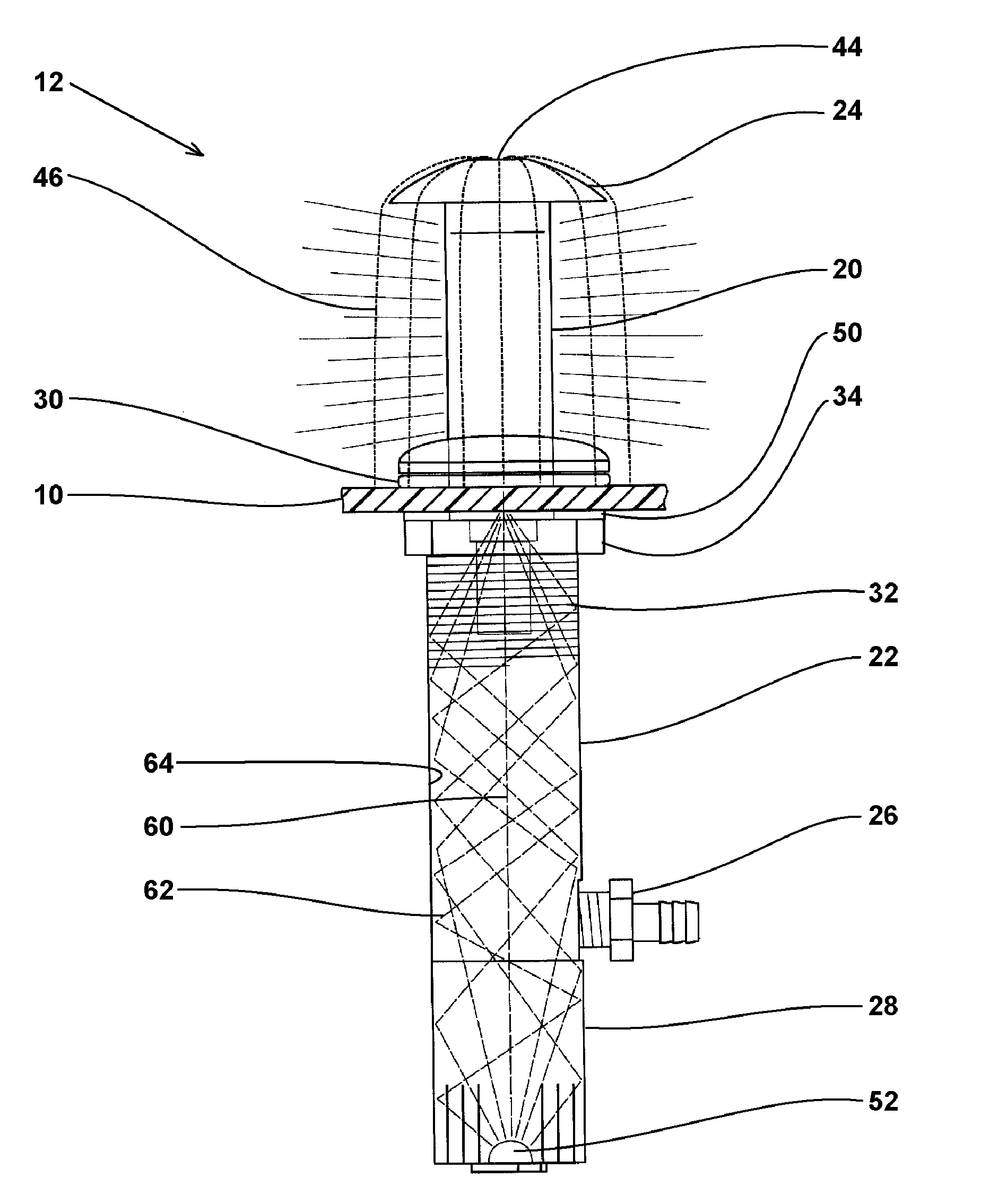
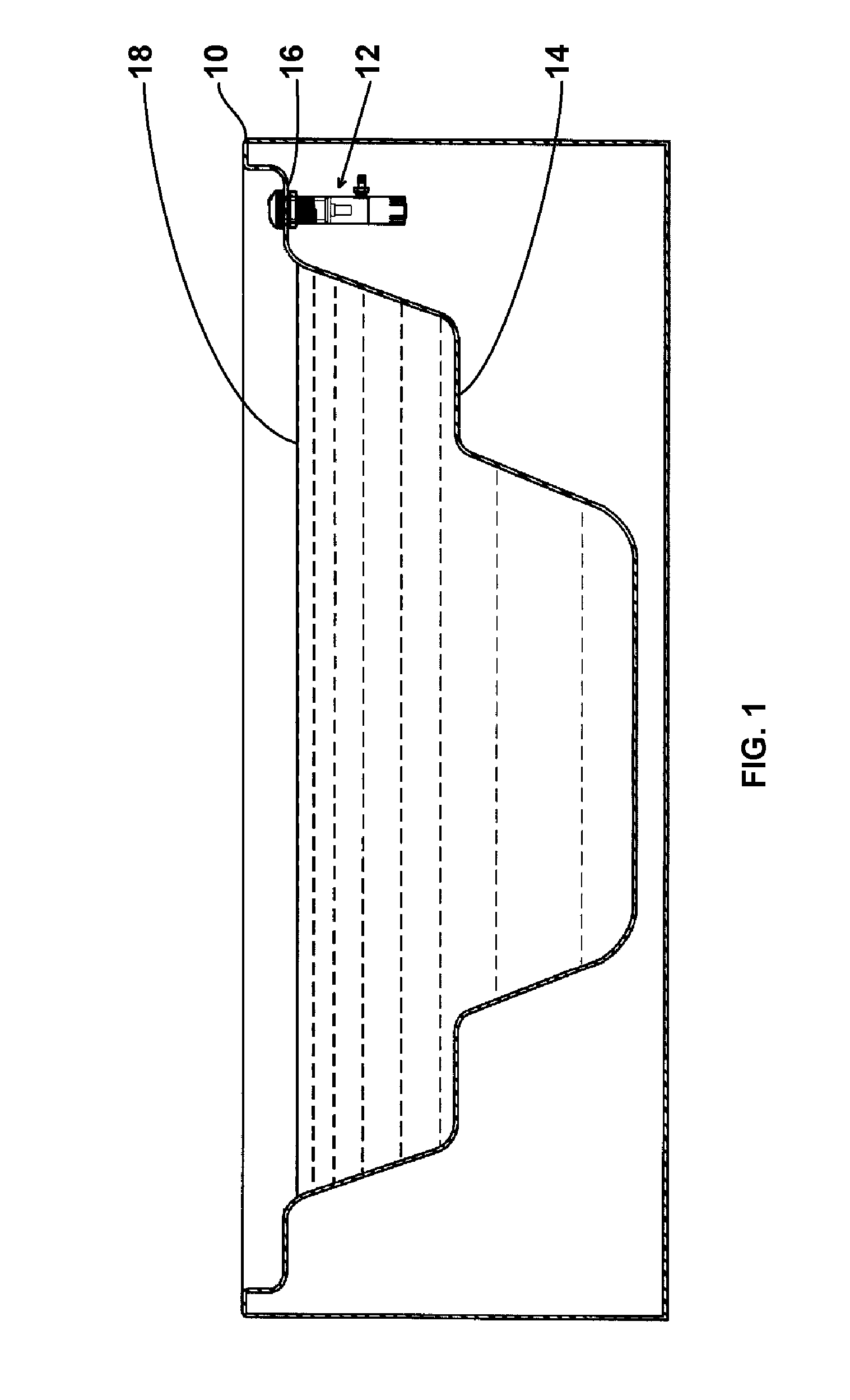
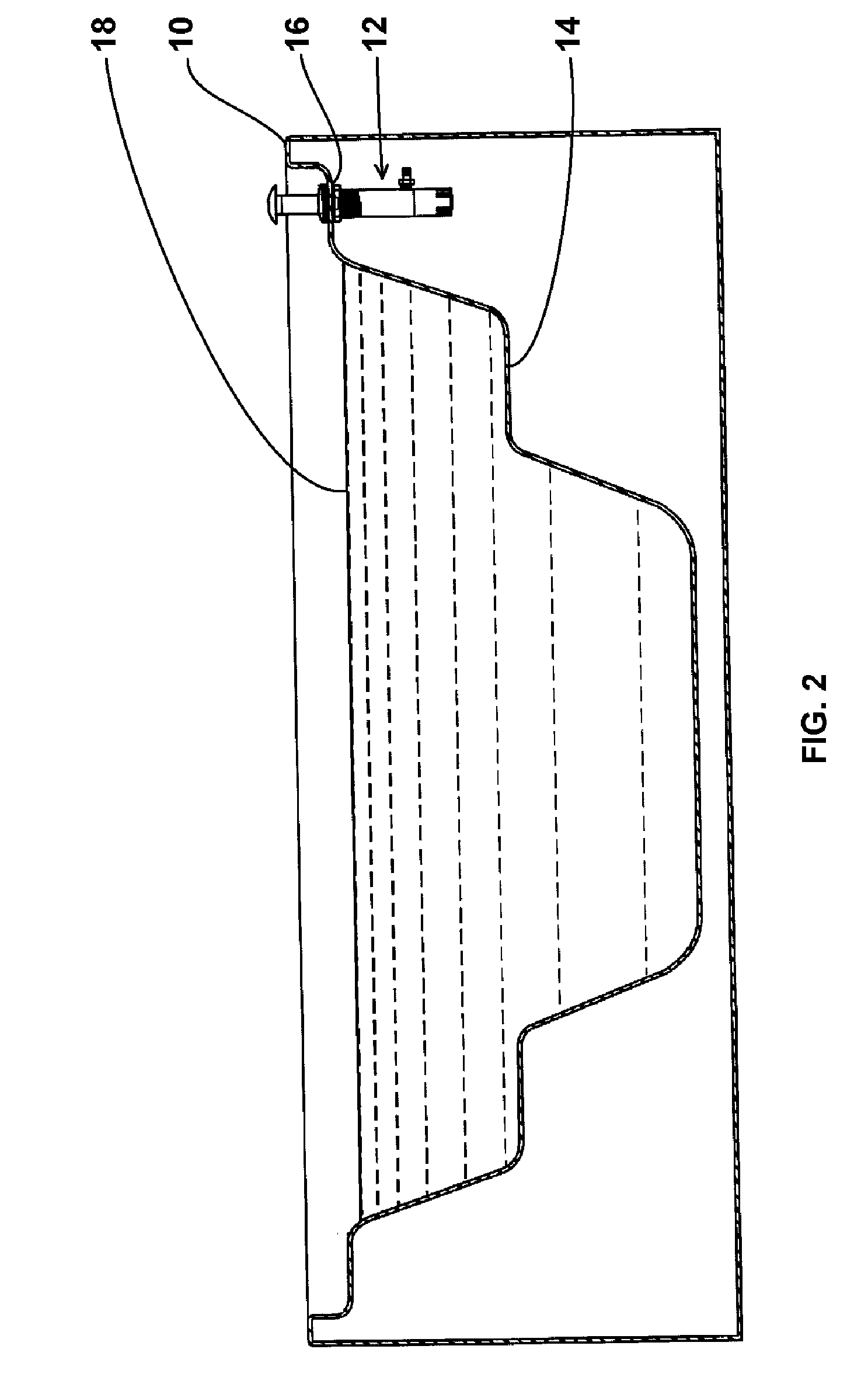
[0027]FIG. 1 is a side view, partly in section, of a spa unit with an embodiment of the waterfall device of the present invention mounted in an illustrative position on the upper ledge of the spa unit and located near, or slightly above, the waterline of the spa unit, and in the retracted or resting position. FIG. 2 is the same view as FIG. 1 showing the waterfall device in the operating or extended position. FIG. 3 is more detailed side view, partly in section, of a spa unit depicted in FIG. 1 showing...


PUM


Abstract

A rising water feature that produces a waterfall into a spa, swimming pool, tub, reservoir, or the like, while the device itself is illuminated. In a resting position, the device is retracted and has a generally flat profile relative to the spa surface. In an operation position, the device is extended above the spa surface.

Description

BACKGROUND OF THE INVENTION[0001]1. Technical Field[0002]The present invention generally is in the field of water features for use in connection with artificial bodies of water, and more particularly is in the field of devices for generating aesthetically pleasing waterfalls in spas, swimming pools, tubs, hydrotherapy equipment, and the like.[0003]2. Related Art[0004]Few applications derive more benefit from the addition of waterfalls, fountains and other water features than artificial bodies of water such as spas, swimming pools, tubs, and other such structures. The popularity of waterfalls, fountains and other water features in such structures is probably associated with the numerous aesthetic and practical applications that make water features desirable. More specifically, the addition of a water feature to an artificial body of water can provide a substantial decorative effect or can provide a relaxing background sound, generated from the water flow. As such, users and owners of...

Claims


Application Information

Patent Timeline
IPC IPC(8): F21V33/00
CPCB05B15/10B05B17/085F21V21/22F21S8/028F21W2121/02F21Y2101/02F21V33/004F21Y2115/10B05B15/74
Inventor VOGTNER, ZACHARY
Owner CUSTOM MOLDED PROD
Why Eureka
Try Eureka