Solar energy system

a solar energy system and solar energy technology, applied in the field of solar energy systems, can solve the problems of extensive plumbing of existing hybrid panels (heat and electric), and achieve the effects of reducing the cost of production, facilitating and inexpensive production, and ensuring the smooth flow through the channel

Active Publication Date: 2022-03-22
TYLL SOLAR
View PDF162 Cites 0 Cited by
  • Summary
  • Abstract
  • Description
  • Claims
  • Application Information

AI Technical Summary

Benefits of technology

[0008]The plates may be formed from a heat conductive material, such as a metal or a polymer, and are oriented in parallel planes with a channel formed between the plates. The plates are juxtaposing disposed, typically securably disposed together, and one plate has an outer flat surface with a photovoltaic cell matrix affixed thereto and that controls the flow of liquid passing through the channel to enhance the heat conduction between the liquid and the plates. The ability to control the volume through channels also serves to maximize thermal transference from the PV cell matrix (which gets hot while generating electricity) to the working fluid within the aforementioned “bladder” by forcing the fluid through the panel for even heat absorption throughout the entire area of the panel. The fluid path and volume were modeled to maximally cool the PV layer to generate the highest electrical output, as opposed to other PVT's that seek to generate the maximum heat for the working fluid (to offer a higher temperature fluid for processes). Advantageously, the present invention targets not maximum fluid temperature but rather maximum electricity, which for the present invention is the higher value of the two and achieves this through innovative fluid flow design, thereby cooling the PV panel more evenly than existing PVT's. Even, uniform cooling of the PV layer is one important consideration for maximum electricity generation.
[0009]The fluid may be introduced into and recovered from the channel by means of header assemblies. The header assemblies may comprise upper and lower flanges with an end manifold sandwiched therebetween. The end manifold has a plurality of nozzles spaced substantially or fully along the length of opposed edges of the plates and in communication with the channel between the plates. As such, the fluid is introduced and removed from the channel in a smooth, even flow. One of the headers acts as an inlet for the fluid into the channel and the other acts as an outlet for the removal of the fluid after it has passed through the channel. In some instances, an additional pipe may be attached or affixed to the header assemblies, for instance, both top and bottom, to act as a feeder pipe. Normally, an installation of solar panels containing a fluid must be provided with both a feeder pipe to supply fluid and a feeder pipe to remove fluid. By incorporating a feeder pipe into each header assembly, it is possible to avoid plumbing each individual solar panel to pre-installed feeder piping. Moreover, quick connecting means may be provided to connect multiple solar panels. Alternately, using a designed external header, or manifold, of the present invention to distribute fluid evenly reduces installation cost significantly and provides cooled fluid to each panel (not connected in series).
[0011]The size of the nozzles in the inlet header is, in the exemplary embodiment, controllable so that the inlet flow can be increased or decreased by an operator to optimize the overall system when used in an array with multiple panels. In addition, the overall or cumulative openings of the nozzles in the outlet header removing fluid from the channel is larger than the overall or cumulative openings in the inlet header so as to maintain a smooth flow through the channel.
[0012]The solar panels of the present invention may be produced easily and inexpensively and, further are easy to assemble. The ease of manufacture and assembly of the solar panels of the present invention provide great advantages in the use of solar panels for producing heat, heated water and electricity. For example, the solar panels of the present invention may have more than 6% greater annual electricity production versus similar conventional PV cell panels without the thermal technology of the present invention.

Problems solved by technology

Additionally, existing hybrid panels (heat and electric) require extensive plumbing both in preparation for an installation (feeder pipes, evacuation pipes) and localized plumbing (plumb each panel to both feeder pipes).

Method used


Image

  • Solar energy system
  • Solar energy system
  • Solar energy system

Examples


Embodiment Construction

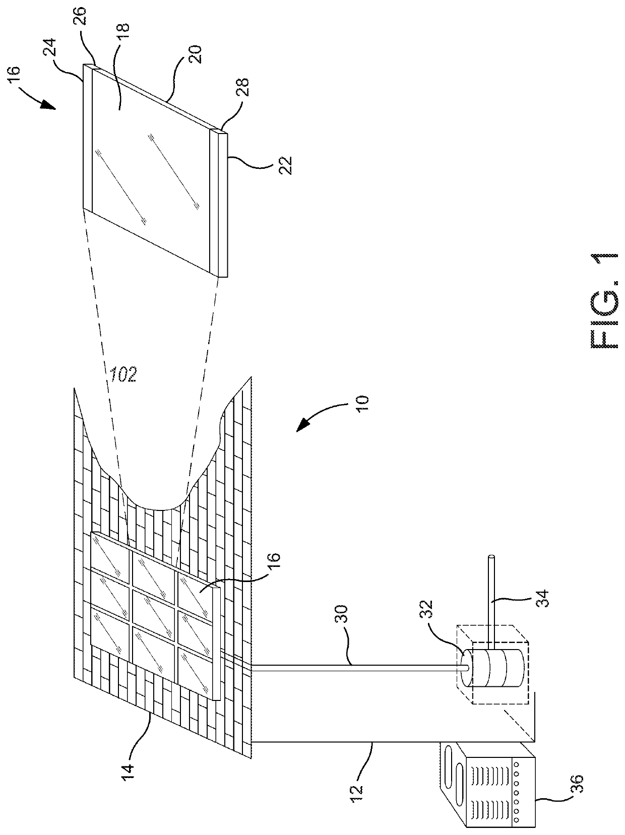
[0037]Turning first to FIG. 1, there is shown a schematic view, partially exploded illustrating a solar energy system 10 constructed in accordance with the present invention. As can be seen, there is a building structure 12 with a roof 14 with an exposure to some form of sunlight, albeit direct or indirect. The building structure 12 can, of course, be any type of building that has a need for electricity and / or heated water. As will be seen, the present invention can be used with a structure that is devoted entirely to the production of heat, heated water and / or electricity i.e. a dedicated structure or frame and not serve any other purpose such as for inhabitants or a structure for housing occupants.

[0038]As seen in FIG. 1, the roof 14 has a plurality of solar panels 16 arranged in columns (vertical alignment) and in rows (lateral alignment). As shown, there are nine (9) solar panels 16, however, as will become clear, the number of panels, their size and orientation may vary dependi...


PUM


Abstract

A modular, solar energy system comprising one or more modular solar panels. The solar panels include a pair of general planar, plates that are secured together to form a narrow channel therebetween for the circulation of a liquid. The solar panels have inlet and outlet fluid lines in fluid communication via manifolds with a cold fluid supply line and a warm fluid return line, respectively. The plates are preferably constructed of aluminum and one plate has a photovoltaic cell matrix affixed thereto to face the sun. The plates have dividers or partitions that enhance the heat transfer characteristics with respect to the liquid flowing though the channel between the plates.

Description

CROSS-REFERENCE TO RELATED APPLICATIONS[0001]This application claims the benefit of U.S. Provisional Application No. 62 / 717,830, filed Aug. 11, 2018, the contents of which are incorporated herein by reference.FIELD OF THE INVENTION[0002]The present invention is in the technical field of solar energy and, more particularly, the present invention is in the technical field of solar energy systems using solar panels for generating heat, hot water and / or electricity.BACKGROUND OF THE INVENTION[0003]There are, at the present, solar energy systems employing solar panels that gather the radiant energy from the sun to either heat fluid circulating there through (solar thermal panels), generate electricity (photovoltaic, or “PV” panels) or both. Panels that generate both electricity and useful heat are called photovoltaic thermal panels (PVT), or “hybrid” panels. An example of such solar panels is shown and described in U.S. patent application Ser. No. 12 / 660,646, filed Mar. 2, 2010 entitled ...

Claims


Application Information

Patent Timeline
Patent Type & Authority Patents(United States)
IPC IPC(8): H02S40/44H02S20/23H02S40/42F24S10/50F24S25/20F24S70/12
CPCH02S40/44F24S10/502F24S25/20F24S70/12H02S20/23H02S40/425F24S2020/17F24S10/503H01L31/048H02S30/10Y02E10/47Y02B10/10
Inventor FISCHER, JAY D.
Owner TYLL SOLAR
Why Eureka
Try Eureka