Sinking electrical card connector

Inactive Publication Date: 2008-04-24
HON HAI PRECISION IND CO LTD
View PDF9 Cites 16 Cited by
  • Summary
  • Abstract
  • Description
  • Claims
  • Application Information

AI Technical Summary

Benefits of technology

[0007] An object, therefore, of the invention is to provide a sinking electrical card connector, which can reli

Problems solved by technology

So the insulating housing tends to deflect forwardly because of the barycenter of the insulating housing away from the soldering portion of the metallic terminals, and the terminals can not be soldered stably with the PCB.
Additional

Method used


Image

  • Sinking electrical card connector
  • Sinking electrical card connector
  • Sinking electrical card connector

Examples


Embodiment Construction

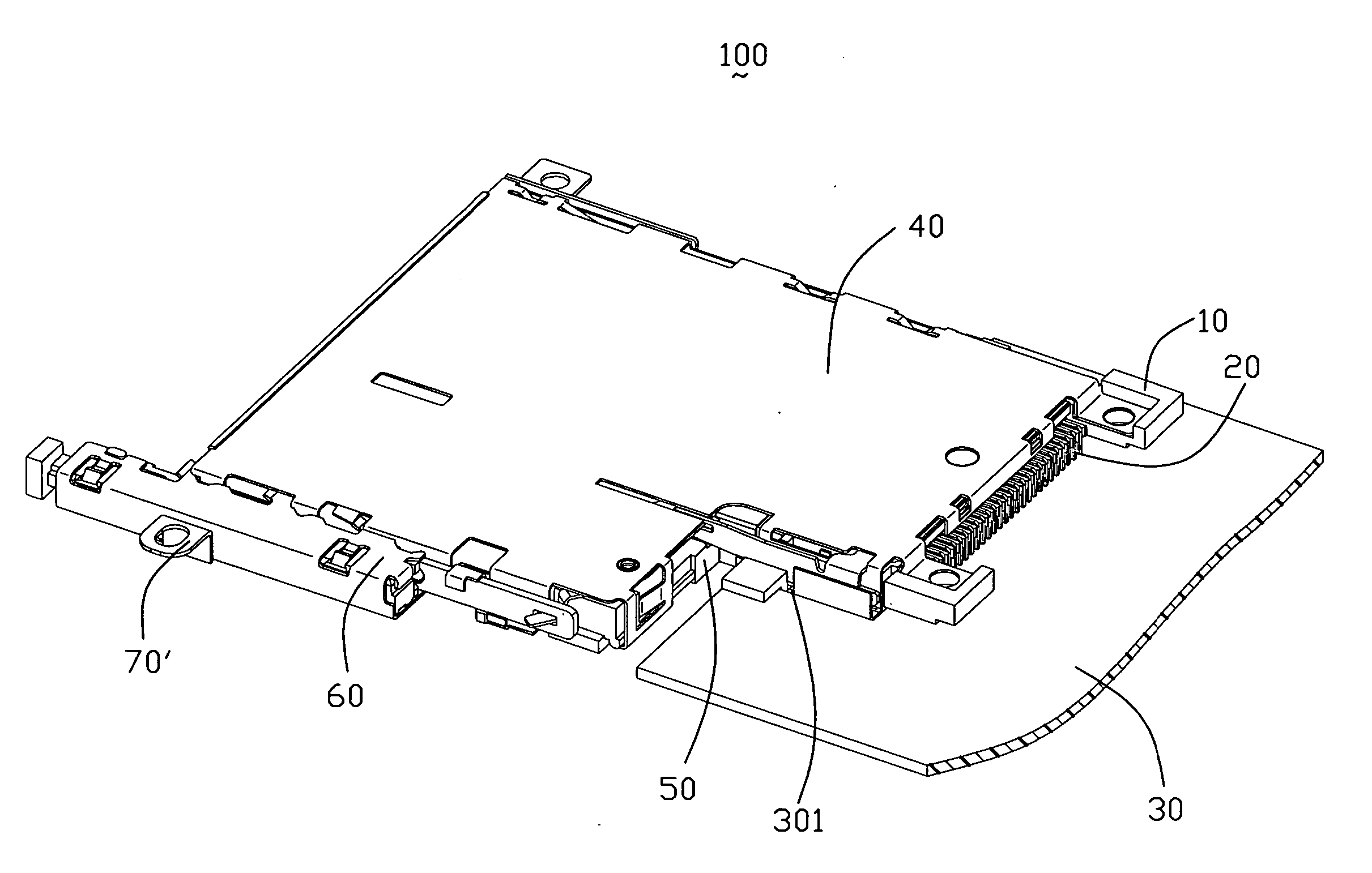
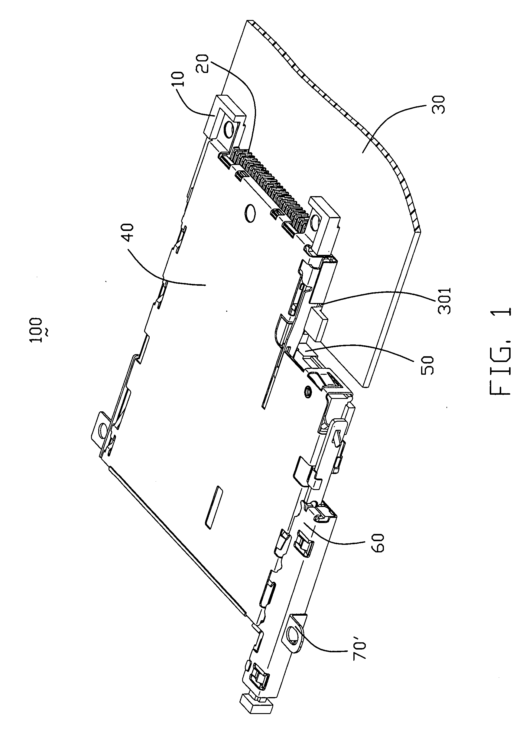
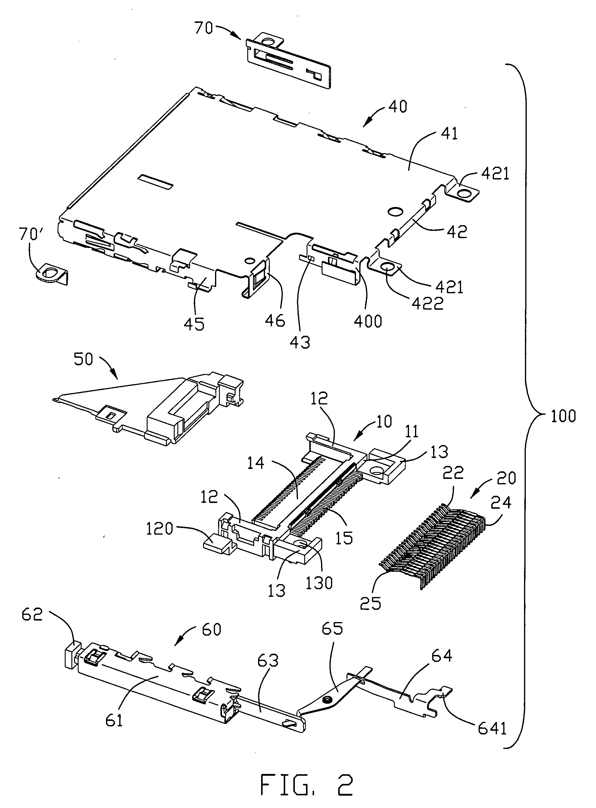
[0016] Referring to the drawings in greater detail, and first to FIGS. 1 and 2, a sinking electrical card connector 100 partially sinking in a hole 301 of a Printed Circuit Board (PCB) 30 in accordance with present invention comprises a generally rectangular insulating housing 10 and a generally L-shaped shell 40 mounted on the insulating housing 10. The insulating housing 10 and the shell 40 define a receiving room (not labeled) for selectively receiving an I-shaped or L-shaped card. A guiding portion 50 is mounted in the receiving room for guiding a card inserted. An ejecting member 60 is mounted on one lateral side of the shell 40. A supporting foot 70 is mounted at a lateral side of the shell 40, and the other supporting foot 70′ is provided on the ejecting member 60.

[0017] With respect to FIG. 2 to FIG. 4, the insulating housing 10, adapted for mounted on the PCB 30, is illustrated in following segments. The insulating housing 10 includes a base section 11, a pair of arms 12 e...


PUM


Abstract

A sinking electrical card connector includes an insulating housing (10) sinking partially into a hole defined on a printed circuit board (30) (PCB), a number of terminals (20) retained in the insulating housing, a shell (40) mounted on the insulating housing, wherein a pair of holding portions 120 and 120′ are formed by the opposite lateral walls of the insulating housing extending outwardly, and each holding portion engages with an edge of the hole of the PCB.

Description

BACKGROUND OF THE INVENTION [0001] 1. Field of the Invention [0002] The present invention relates to an electrical card connector for accessing electrical cards, such as memory cards, and more particularly to a sinking electrical card connector partially sinking into a hole provided on a Printed Circuit Board (PCB). [0003] 2. Description of Prior Arts [0004] Memory cards are used in many applications in today's electronic society, including video cameras, smartphones, music players, ATMs, cable television decoders, toys, games, PC adapters and other electronic applications. A typical memory card includes a contact or terminal array for connecting an electrical connector to a card reader system and then to external equipment. The connector readily accommodates insertion and removal of the card to provide quick access to the information and program on the card. The card connector includes terminals for engaging the contact or terminal array of the card. U.S. Pat. No. 7,090,513, for ex...

Claims


Application Information

Patent Timeline
IPC IPC(8): H01R13/62
CPCH01R12/721Y10S439/947H01R13/6595Y10S439/945Y10S439/951
Inventor CHENG, YUNG-CHANG
Owner HON HAI PRECISION IND CO LTD
Why Eureka
Try Eureka