
Pneumatic tire and method of mounting transponder to pneumatic tire

Inactive Publication Date: 2011-05-26
YOKOHAMA RUBBER CO LTD
View PDF7 Cites 3 Cited by
  • Summary
  • Abstract
  • Description
  • Claims
  • Application Information

AI Technical Summary

Benefits of technology

[0010]The present invention makes it possible to prevent a large centrifugal force and a large impact force from acting upon the transponder mounted on a pneumatic tire, and to remarkably reduce the weight of a transponder for storing various pieces of information and the weight of a securing member for securing the transponder. Thereby, the present invention makes it possible to easily correct a dynamic balance of the tire as well as to enhance uniformity of the tire. Furthermore, the mounting can be done faster and more reliably than through the fixation by adhesion. Even in a case of a large tire, reduction in durability of the tire can be minimized through suppressing heat generation and heat accumulation of the tire due to the transponder and the securing member.
[0042]In a case where a securing screw member is used for the securing member, the mounting can be done faster and more reliably than through the fixation by adhesion. Moreover, with a mechanical fastening method by a screw, a joining strength can be made stronger than through the fixation by adhesion.

Problems solved by technology

In a case where a transponder is fixed to an inner surface of a tire by adhesion, there is a possibility that a fixation status thereof is unreliable depending on how the fixation is performed.
In this structure, however, unbalanced tire weight occurring due to the transponder 1 and the screw member is large, the transponder 1 being attached to the interior of the pneumatic tire on the equatorial plane thereof, and the screw member securing the transponder.
As a result, correction of the unbalanced weight is extremely difficult, and there is a problem that a tire uniformity is deteriorated.
As a result, there is a problem that this leads to reduction in durability of the transponder.
There is also a problem that it is difficult to secure the transponder to the pneumatic tire which is made of a rubber member, and which undergoes a relatively large deformation.

Method used


Image

  • Pneumatic tire and method of mounting transponder to pneumatic tire
  • Pneumatic tire and method of mounting transponder to pneumatic tire
  • Pneumatic tire and method of mounting transponder to pneumatic tire

Examples


example 1

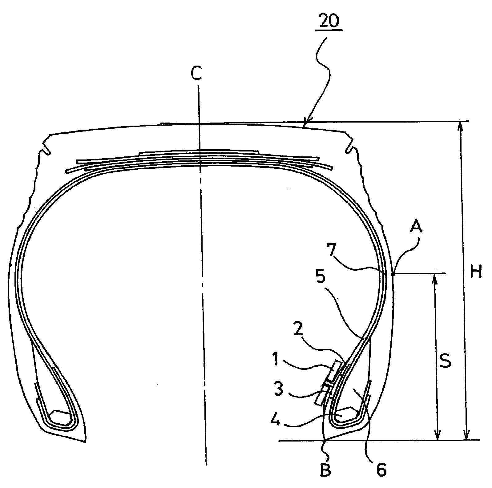
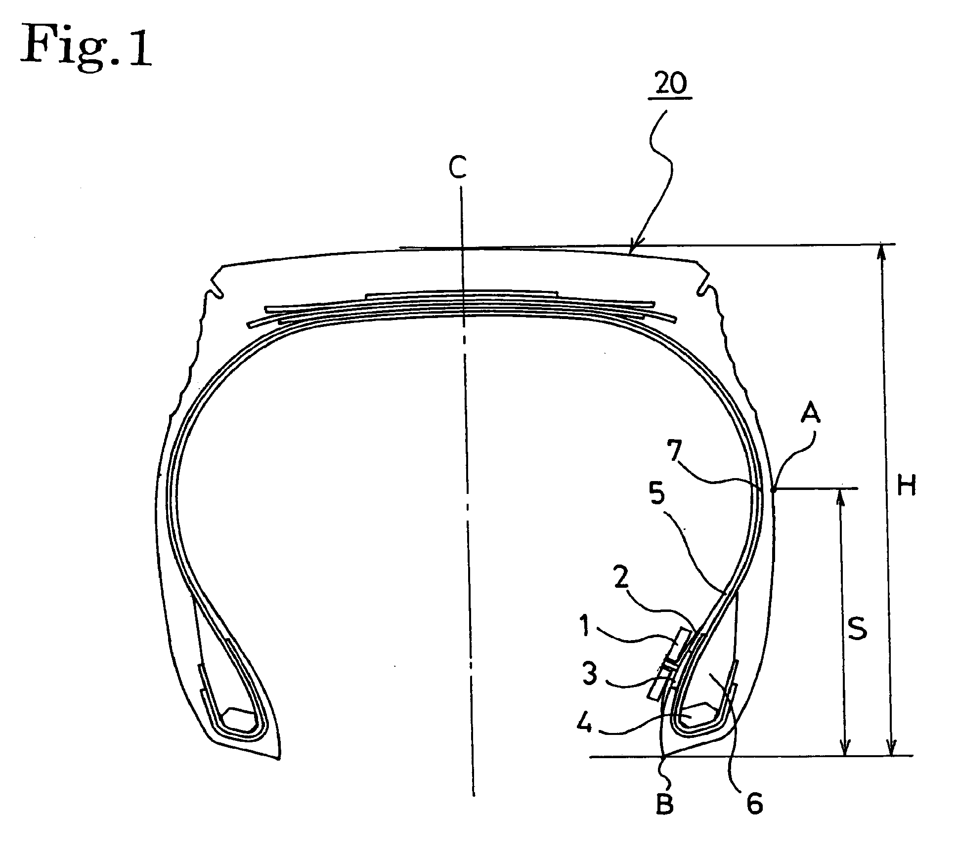
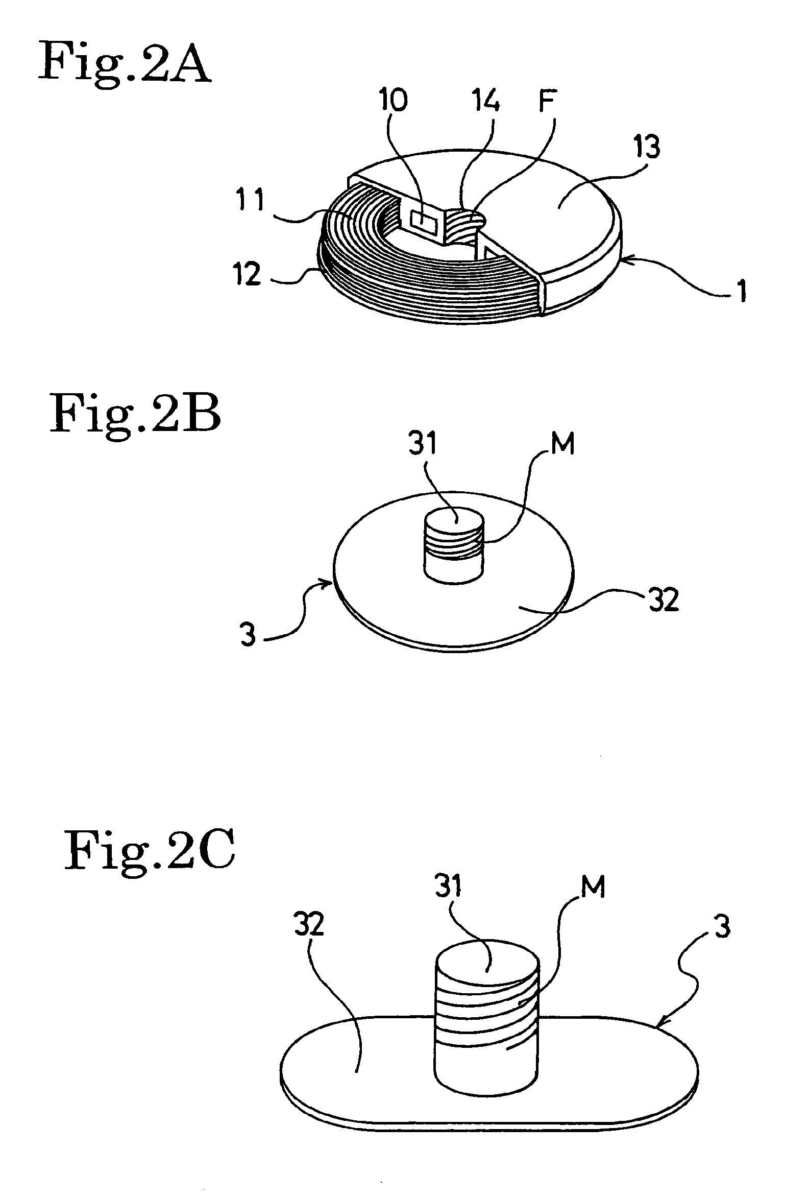
[0129]As Example 1 of the pneumatic tire of the first embodiment, the securing screw member 3 having the male screw M was fixed with the patch 2 to a location 40 mm away from the bead toe A toward an outer circumference of the tire as shown in FIG. 1. As shown in FIG. 2A, the cylindrical transponder 1 which has an outer diameter of 20 mmΦ and a thickness of 3 mm was screwed to this male screw M by use of screws respectively of the transponder 1 and of the mail screw M. In this manner, 20 units of the pneumatic tires 20 of 11R22.5 16PR having a pattern for traveling on a general paved road were prepared.

[0130]Note that this transponder 1 is provided with the female screw F at the center thereof, on an inner surface of the through hole 14 having an outer diameter of 3 mmΦ, and is covered with bisphenol A type epoxy resin having a Shore D hardness of 96, and a decomposition-start temperature of 300° C.

[0131]Moreover, a large housing 60 configured to embrace the transponder 1 as in Exam...

example 2

[0135]As Example 2 of the pneumatic tire of the fourth embodiment, the string-shaped projection portion 40 was fixed to a location 40 mm away from the bead toe B toward an outer circumference of the tire as shown in FIGS. 7 and 10. An outer diameter of the bottom edge of the truncated-cone shape of the fall-out prevention portion 43 was set at 4 mm, the fall-out prevention portion 43 being provided 3 mm away from a patch portion 31 of the string-shaped projection portion 40.

[0136]The transponder 1 shown in FIG. 8 was formed to have an outer diameter of 20 mmΦ and a thickness of 3 mm, and was provided with the through hole 14A at the center thereof, the through hole 14A having an outer diameter of 3 mmΦ. In this manner, the pneumatic tire 20 of 11R22.5 16PR having a pattern for traveling on a general paved road was prepared. Note that this transponder 1 was formed of a material having a Shore D hardness of 96, and was covered with bisphenol A type epoxy resin having a decomposition-s...


PUM

PropertyMeasurementUnit
Frequencyaaaaaaaaaa
Frequencyaaaaaaaaaa
Areaaaaaaaaaaa

Abstract

In a pneumatic tire (20) on which a transponder (1) is mounted, a securing member (3) for securing the transponder (1) is fixed to an inner surface of the tire in an area (S) between a tire maximum-width position (A) and a bead toe (B). Thereby, a large centrifugal force and a large impact force do not act on the transponder (1) storing various pieces of information, and the transponder can be mounted quickly and securely. Also, the weight of the transponder is remarkably reduced, and thus uniformity of the tire (20) is enhanced. Additionally, dynamic balance correction is made easier. Even in a large tire, reduction in durability is minimized through suppressing heat generation and heat accumulation of the tire (20) due to the transponder (1) and the securing member (3).

Description

[0001]This is a divisional of application Ser. No. 11 / 663,290, filed Mar. 20, 2007.TECHNICAL FIELD[0002]The present invention relates to a pneumatic tire to which a member for mounting a transponder is fixed, and a method of mounting the transponder on the pneumatic tire. More specifically, the present invention relates to a pneumatic tire that enables a transponder to be securely mounted thereon, and that enables imbalance in weight to be securely reduced, and the present invention also relates to a method of mounting the transponder on the pneumatic tire. The transponder is that for measuring at least an internal pressure of the tire and for storing various pieces of information. The imbalance in weight is due to a securing member and the transponder.BACKGROUND ART[0003]Technologies have been actively developed for mounting a transponder on a tire in order for a tire manufacturer to manage its manufacture of a tire, in order for a tire purchaser to manage use history of his / her ti...

Claims


Application Information

Patent Timeline
IPC IPC(8): H01P11/00
CPCB29D2030/0072B60C23/0493Y10T29/49016Y10T152/10495Y10T156/10H01Q1/2241
Inventor SHIMURA, KAZUHIRO
Owner YOKOHAMA RUBBER CO LTD
Learn More