Rail adjustment system for a motor vehicle seat

a technology for motor vehicles and rails, which is applied in the direction of machine supports, roofs, other domestic objects, etc., can solve the problems of complex production, unfavorable noise generation, and inability to adjust the rails, so as to achieve the effect of reliably suppressing the creation of vibrational noise and simple manner

Active Publication Date: 2012-12-11
BROSE FAHRZEUGTEILE GMBH & CO KG
View PDF28 Cites 10 Cited by
  • Summary
  • Abstract
  • Description
  • Claims
  • Application Information

AI Technical Summary

Benefits of technology

[0005]The invention is based on the object of specifying an improved rail adjustment system of the type mentioned in the introduction. A particular aim is to provide a suitable guide for a flexible drive shaft while at the same time creating as little noise as possible.
[0010]The retaining element is therefore expediently produced from plastic and preferably in the form of an injection-molded part. In this case, the retaining element suitably has a lattice structure which flanks both sides of the guide duct. A stable, bending- and twisting-resistant retaining element can be produced in a material-saving manner in this way. Retaining lugs at both ends of the retaining element permit them to be fixed to rails which are situated opposite and at a distance from one another, in particular to their upper rails.
[0012]The advantages achieved by the invention are, in particular, that reliable guidance and mounting of the drive shaft are ensured in a simple manner by the arrangement of a rotation-resistant, but otherwise flexible, drive shaft in a guide duct of a retaining element or carrier part which is arranged between the rails of a rail pair of a motor vehicle seat. In addition, noise creation which is associated with such a drive system, in particular a spindle drive, is avoided or at least considerably reduced. This is of considerable importance in terms of comfort, especially since the drive system is usually positioned relatively close to the user beneath the corresponding vehicle seat, and there under the seat surface.
[0014]Particularly reliable integrated motor and shaft mounting and shaft guidance are provided by the guide duct being formed within the retaining element in the form of support rows, which are offset in relation to one another, of expediently web-like support elements and support gaps which are arranged one behind the other and such that they alternate and are suitably integrally formed in a retaining element which is in the form of a plastic structural part. This permits threading of the flexible drive shaft into and out of the guide duct, which is in the form of a support structure, in a simple manner for mounting purposes, particularly in the case of initial mounting and also for repair purposes.
[0016]The resulting grid-like support structure, which is accordingly formed at points, of the correspondingly formed support or guide duct for the flexible drive shaft can therefore be mounted in this specially configured guide duct in a particularly simple manner. The creation of vibrational noise is reliably suppressed on account of the suitable stabilization of the position of the drive shaft.

Problems solved by technology

While the provision of an additional support tube for the flexible drive shaft entails increased outlay on parts, a flexible drive shaft, whose flexible casing tube is provided with support points for the rotating core, is complicated in terms of production.
In addition, rail adjustment systems whose spindle drives are equipped with drive shafts of this type have a tendency to create undesirable noise.

Method used


Image

  • Rail adjustment system for a motor vehicle seat
  • Rail adjustment system for a motor vehicle seat
  • Rail adjustment system for a motor vehicle seat

Examples


Embodiment Construction

[0022]Corresponding parts are provided with the same reference symbols in all the figures.

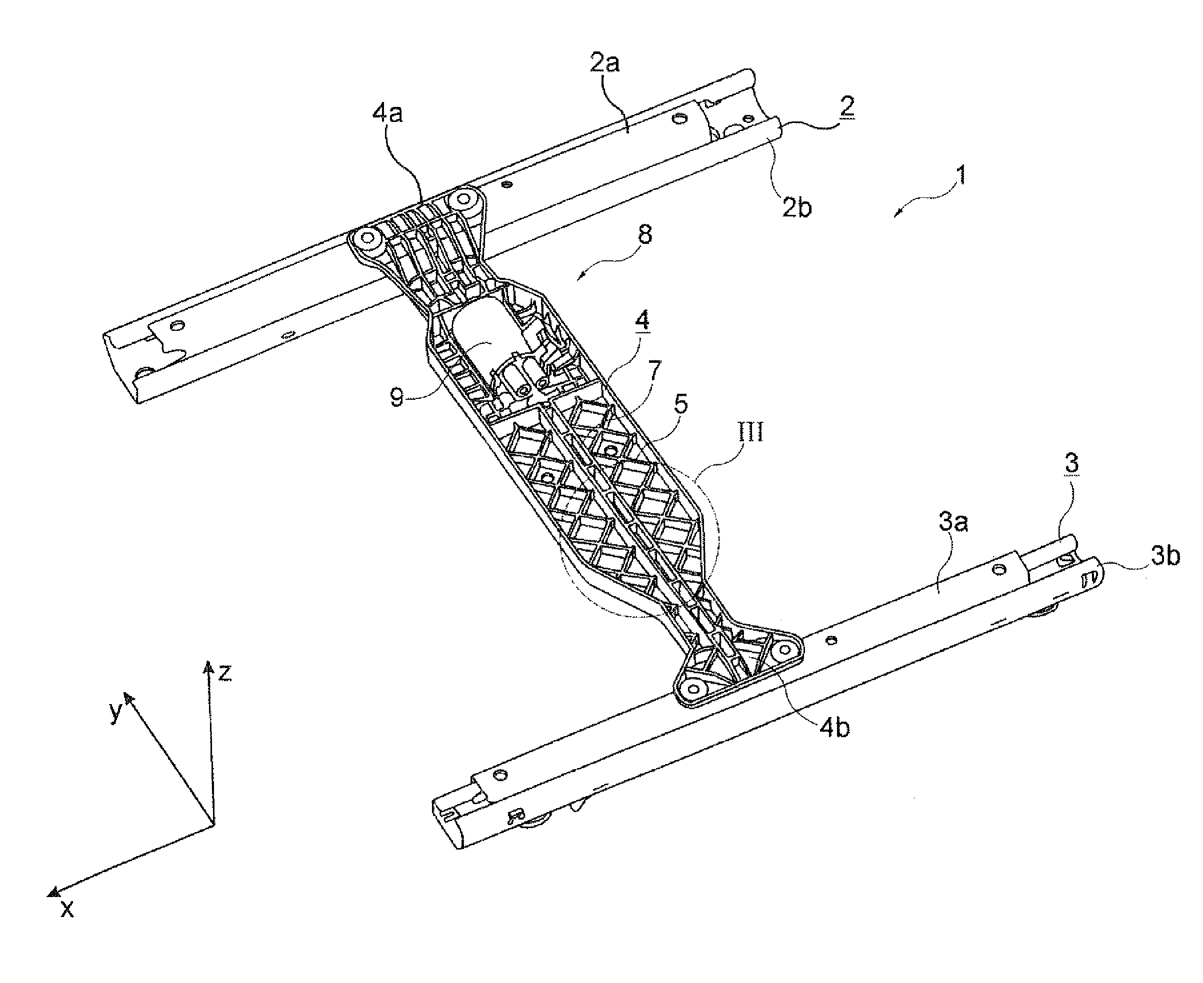
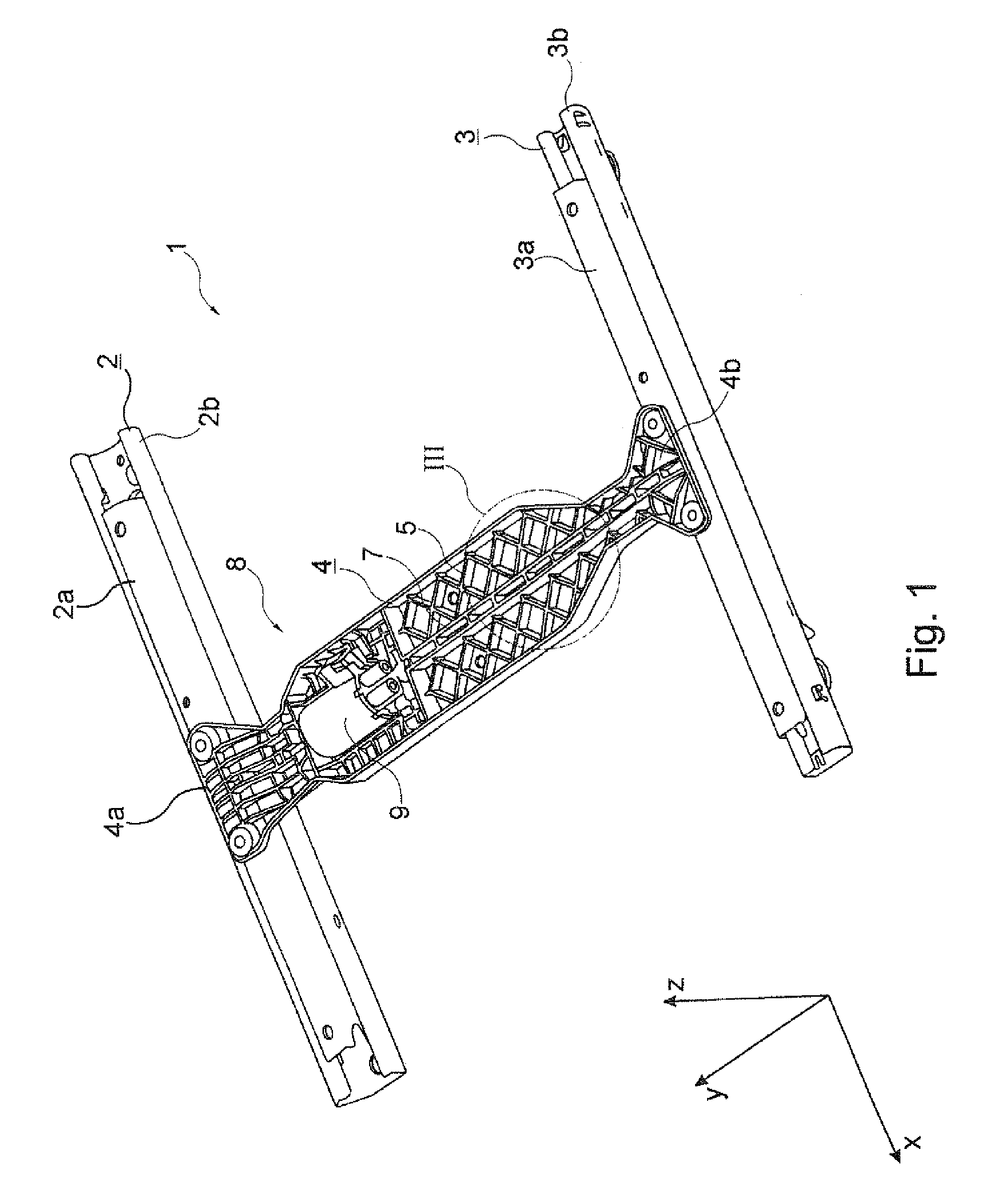
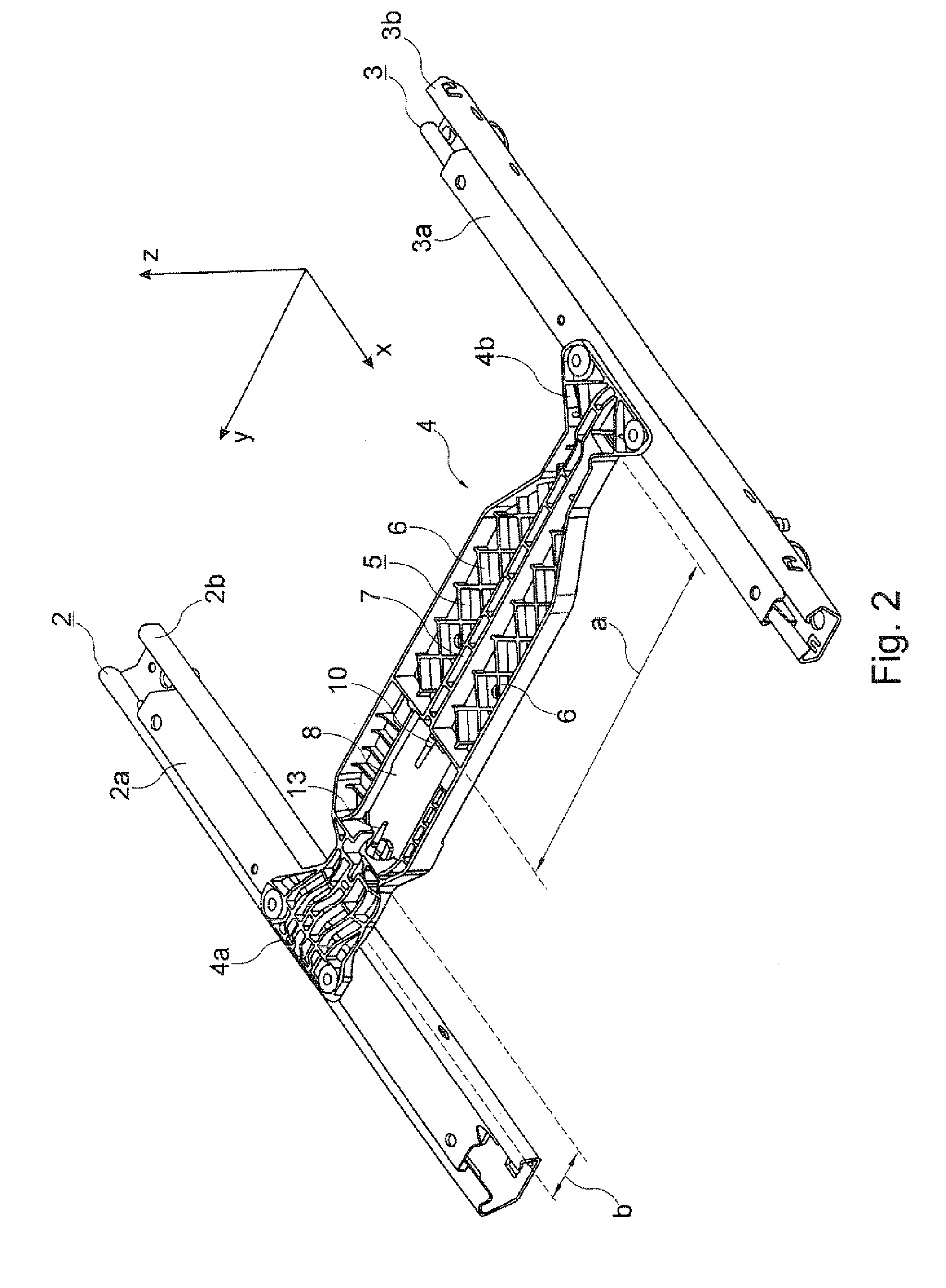
[0023]FIGS. 1 and 2 show a rail adjustment system 1 for a motor vehicle seat, comprising a rail pair whose rails 2, 3, which are situated opposite and at a distance from one another and run parallel to one another, each comprise an upper rail 2a, 3a and a lower rail 2b or 3b. A carrier part, which is called retaining element 4 in the text which follows, is connected to the upper rails 2a, 3a.

[0024]Based on a vehicle coordinate system, the upper rails 2a, 3a can be longitudinally displaced in the x-direction in relation to the lower rails 2b or 3b which are fixed to the floor of the vehicle. The retaining element 4 therefore extends in the y-direction, that is to say transverse to the rails 2, 3. A vehicle seat (not illustrated) and a corresponding seat frame are fixed to the upper rails 2a, 3a.

[0025]The retaining element 4 is a plastic injection-molded part. It has retaining lugs 4a, 4b at bo...


PUM


Abstract

The invention relates to a rail adjustment system for a motor vehicle seat, wherein the rail adjustment system includes an electromotive spindle drive and a threaded spindle that can be coupled to a flexible drive shaft for the longitudinal adjustment of a rail pair. The rails of said rail pair are connected to one another by means of a retaining element, which includes an integrated guide duct for holding the drive shaft.

Description

FIELD OF THE INVENTION[0001]The invention relates to a rail adjustment system for a motor vehicle seat, comprising a spindle drive and comprising a flexible drive shaft which can be coupled to a threaded spindle for the longitudinal adjustment of a rail pair whose rails are connected to one another by means of a retaining element.BACKGROUND OF THE INVENTION[0002]A rail adjustment system of this type, as is known from DE 198 15 283 C2 for example, comprises a drive motor which is fixed, centrally between two rails of a seat rail pair, to a mounting plate which is connected to the upper rails of said rails. Both sides of the drive motor are connected to a spindle nut which is mounted in a spindle gear mechanism by means of drive shafts which can also be designed as flexible shafts. Said spindle nut interacts with a threaded spindle which is arranged between an upper rail, which can be displaced in the longitudinal direction, and a lower rail which is stationary or fixed to the floor. ...

Claims


Application Information

Patent Timeline
Patent Type & Authority Patents(United States)
IPC IPC(8): F16M13/00
CPCB60N2/0232B60N2/067B60N2/0705B60N2002/0236B60N2002/024B60N2/02258B60N2/02253B60N2/02246
Inventor KOSTIN, SERGEJ
Owner BROSE FAHRZEUGTEILE GMBH & CO KG
Why Eureka
Try Eureka