
Expandable medical device with beneficial agent concentration gradient

a technology of beneficial agents and gradients, applied in the field of expandable, non-removable devices, can solve the problems of increasing trauma, increasing patient risk, and restenosis as a major complication

Inactive Publication Date: 2008-04-24
INNOVATIONAL HLDG LLC
View PDF99 Cites 131 Cited by
  • Summary
  • Abstract
  • Description
  • Claims
  • Application Information

AI Technical Summary

Benefits of technology

"The invention is about a method for making an implantable medical device that releases therapeutic agents. The method involves creating a matrix of the therapeutic agent mixed with a polymeric binder and then applying it to the device in two stages. The concentration of the therapeutic agent in the matrix is different in the two stages, resulting in a continuous gradient of the therapeutic agent in the device. This method allows for controlled and targeted release of therapeutic agents from the implantable medical device."

Problems solved by technology

Restenosis is a major complication that can arise following vascular interventions such as angioplasty and the implantation of stents.
To treat this condition, additional revascularization procedures are frequently required, thereby increasing trauma and risk to the patient.

Method used


Image

  • Expandable medical device with beneficial agent concentration gradient
  • Expandable medical device with beneficial agent concentration gradient
  • Expandable medical device with beneficial agent concentration gradient

Examples


Embodiment Construction

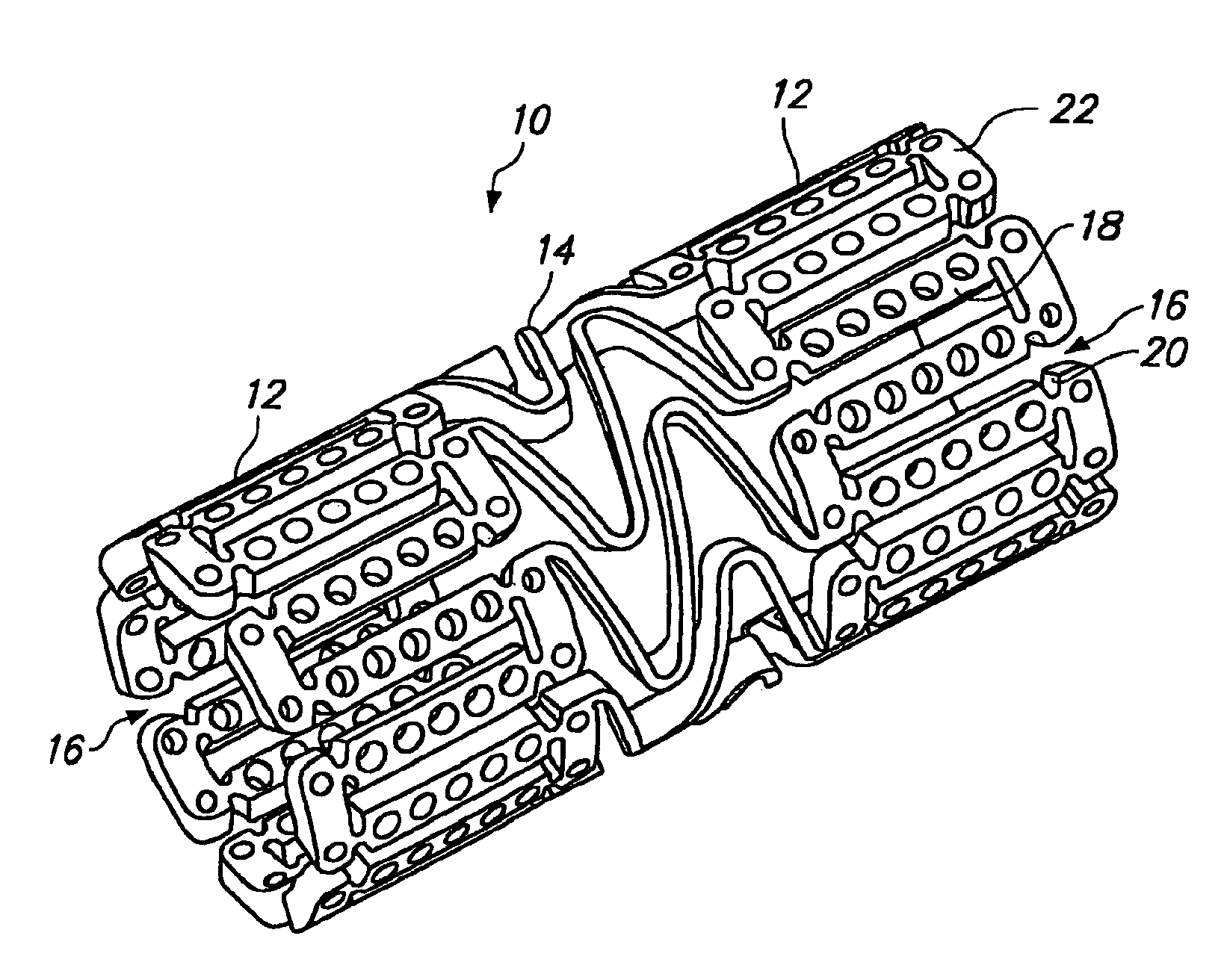
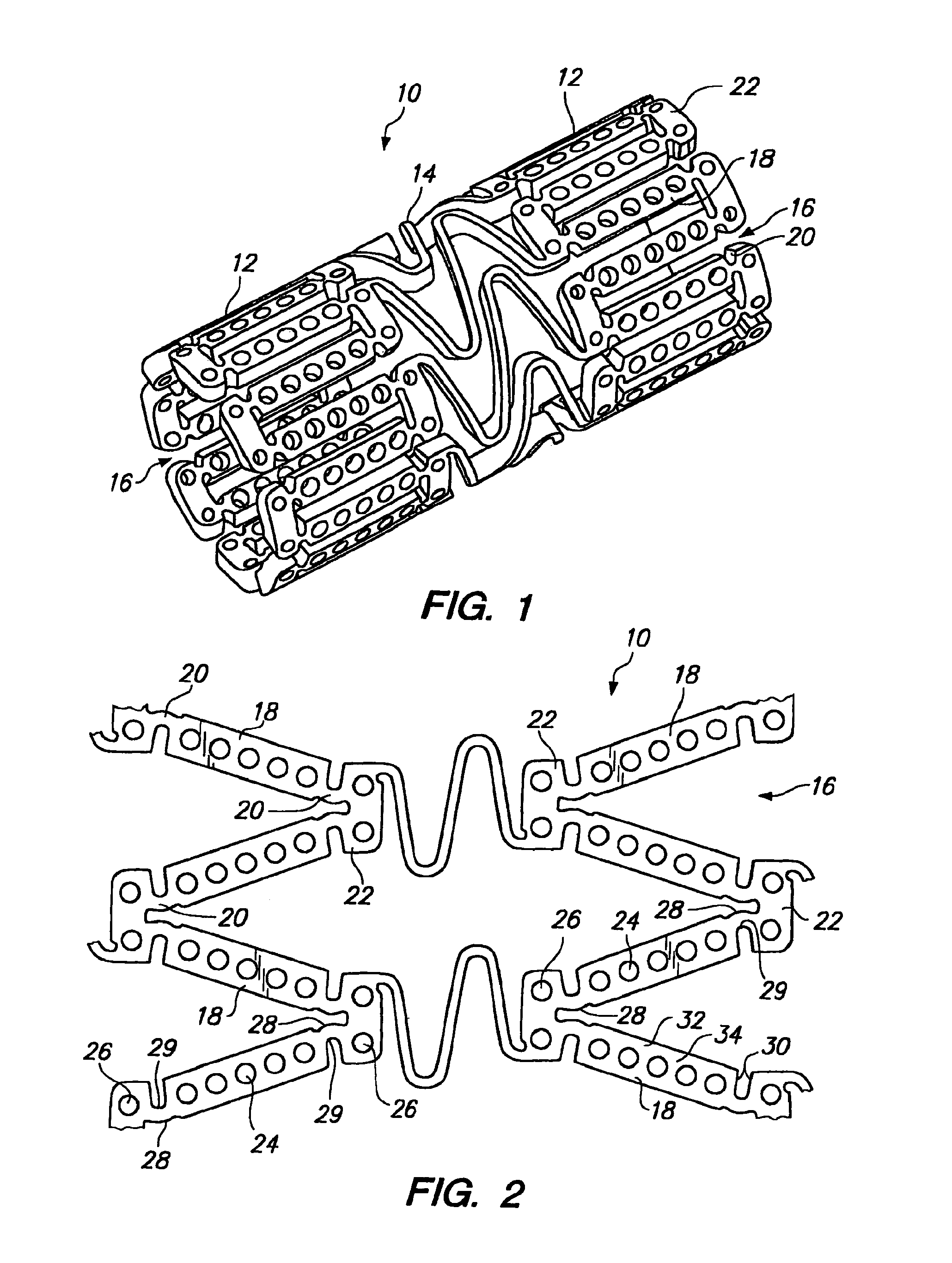
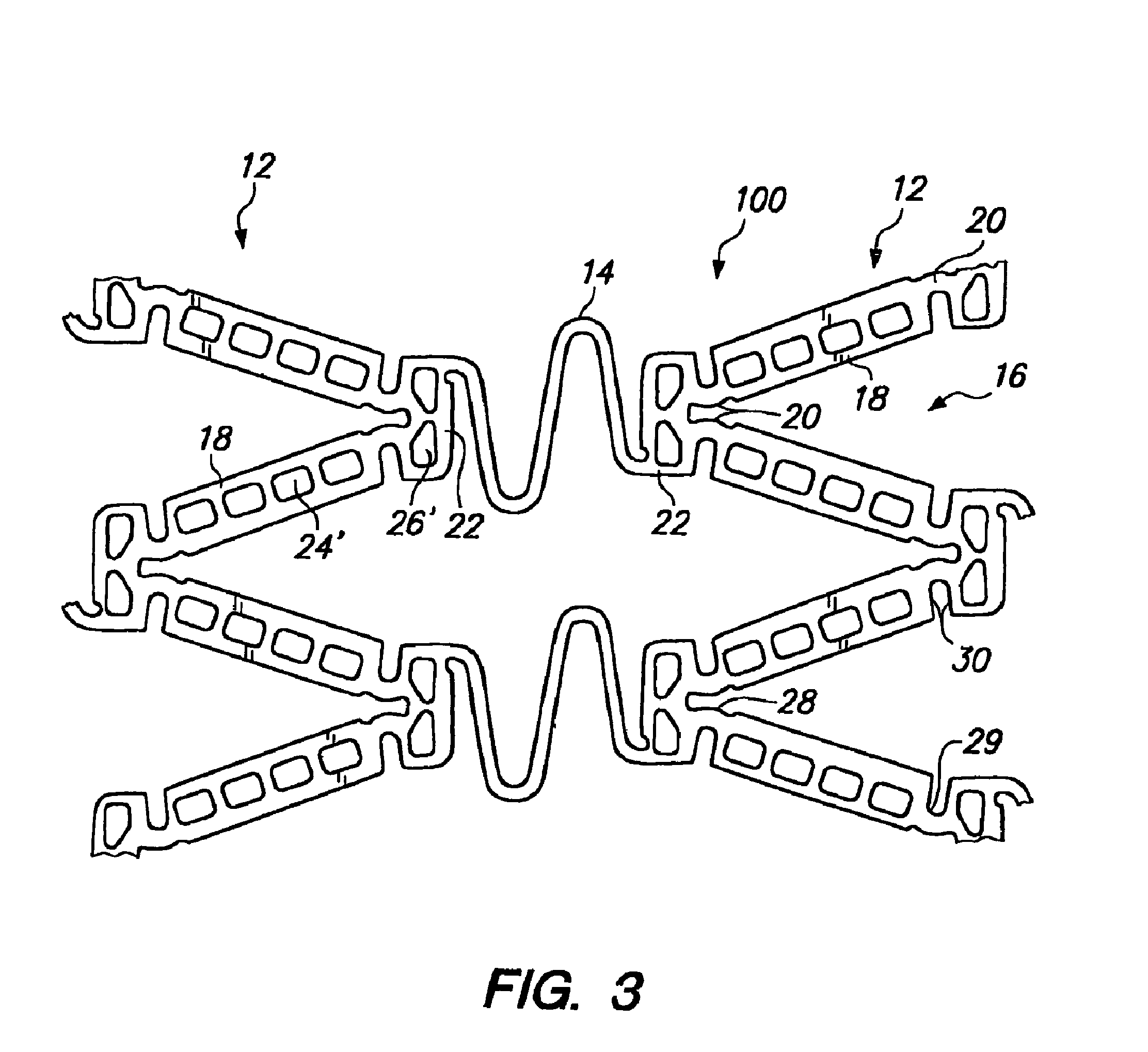
[0039] Referring to FIGS. 1 and 2, a tissue supporting device in accordance with one preferred embodiment of the present invention is shown generally by reference numeral 10. The tissue supporting device 10 includes a plurality of cylindrical tubes 12 connected by S-shaped bridging elements 14. The bridging elements 14 allow the tissue supporting device to bend axially when passing through the tortuous path of the vasculature to the deployment site and allow the device to bend when necessary to match the curvature of a vessel wall to be supported. Each of the cylindrical tubes 12 has a plurality of axial slots 16 extending from an end surface of the cylindrical tube toward an opposite end surface.

[0040] Formed between the slots 16 is a network of axial struts 18 and links 22. The struts 18 and links 22 are provided with openings for receiving and delivering a beneficial agent. As will be described below with respect to FIGS. 9-17, the beneficial agent is loaded into the openings in...


PUM

PropertyMeasurementUnit
widthaaaaaaaaaa
thicknessaaaaaaaaaa
thicknessaaaaaaaaaa

Abstract

An expandable medical device has a plurality of elongated struts joined together to form a substantially cylindrical device, which is expandable from a cylinder having a first diameter to a cylinder having a second diameter. At least one of the plurality of struts includes at least one opening extending at least partially through a thickness of the strut. A beneficial agent is loaded into the opening within the strut in layers to achieve desired temporal release kinetics of the agent. Alternatively, the beneficial agent is loaded in a shape which is configured to achieve the desired agent delivery profile. A wide variety of delivery profiles can be achieved including zero order, pulsatile, increasing, decrease, sinusoidal, and other delivery profiles.

Description

[0001] This application is a continuation of, and claims priority under 35 U.S.C. §120 to, U.S. application Ser. No. 10 / 857,201 (CMI-5001USCIP5), filed 27 May 2004, which is a continuation-in-part of U.S. application Ser. No. 10 / 668,430 (CMI-5007USNP1), filed Sep. 22, 2003, which claims priority to U.S. Provisional Application No. 60 / 412,489 (CMI-5007USUSP), filed Sep. 20, 2002. U.S. application Ser. No. 10 / 857,201 is also a continuation-in-part of U.S. application Ser. No. 10 / 253,020 (CMI-5007-USCIP4), filed on Sep. 23, 2002, now U.S. Pat. No. 7,208,011, which is a continuation-in-part of U.S. application Ser. No. 09 / 948,989 (CMI-5007USCIP7), filed on Sep. 7, 2001, now U.S. Pat. No. 7,208,010, which claims priority to U.S. Provisional Application No. 60 / 314,259 (CMI-5001USPSP1), filed Aug. 20, 2001, and which is a continuation-in-part of U.S. application Ser. No. 09 / 688,092 (CMI-5001USCIP2), filed Oct. 16, 2000 (now abandoned), which is a continuation-in-part of U.S. application Se...

Claims


Application Information

Patent Timeline
Patent Type & Authority Applications(United States)
IPC IPC(8): A61F2/06A61F2/00A61F2/82A61L31/10A61L31/14A61L31/16
CPCA61F2/856A61L2300/602A61F2/915A61F2002/821A61F2002/91508A61F2002/91516A61F2002/91525A61F2002/91533A61F2002/91541A61F2002/91558A61F2250/0035A61F2250/0068A61L31/10A61L31/146A61L31/148A61L31/16A61L2300/416A61F2/91
Inventor SHANLEY, JOHN F.
Owner INNOVATIONAL HLDG LLC
Learn More