
Semi-locking license plate holder

Inactive Publication Date: 2008-05-01
REAL CARBON FIBER LLC D B A ZERO 261 DESIGN GRP
View PDF11 Cites 17 Cited by
  • Summary
  • Abstract
  • Description
  • Claims
  • Application Information

AI Technical Summary

Benefits of technology

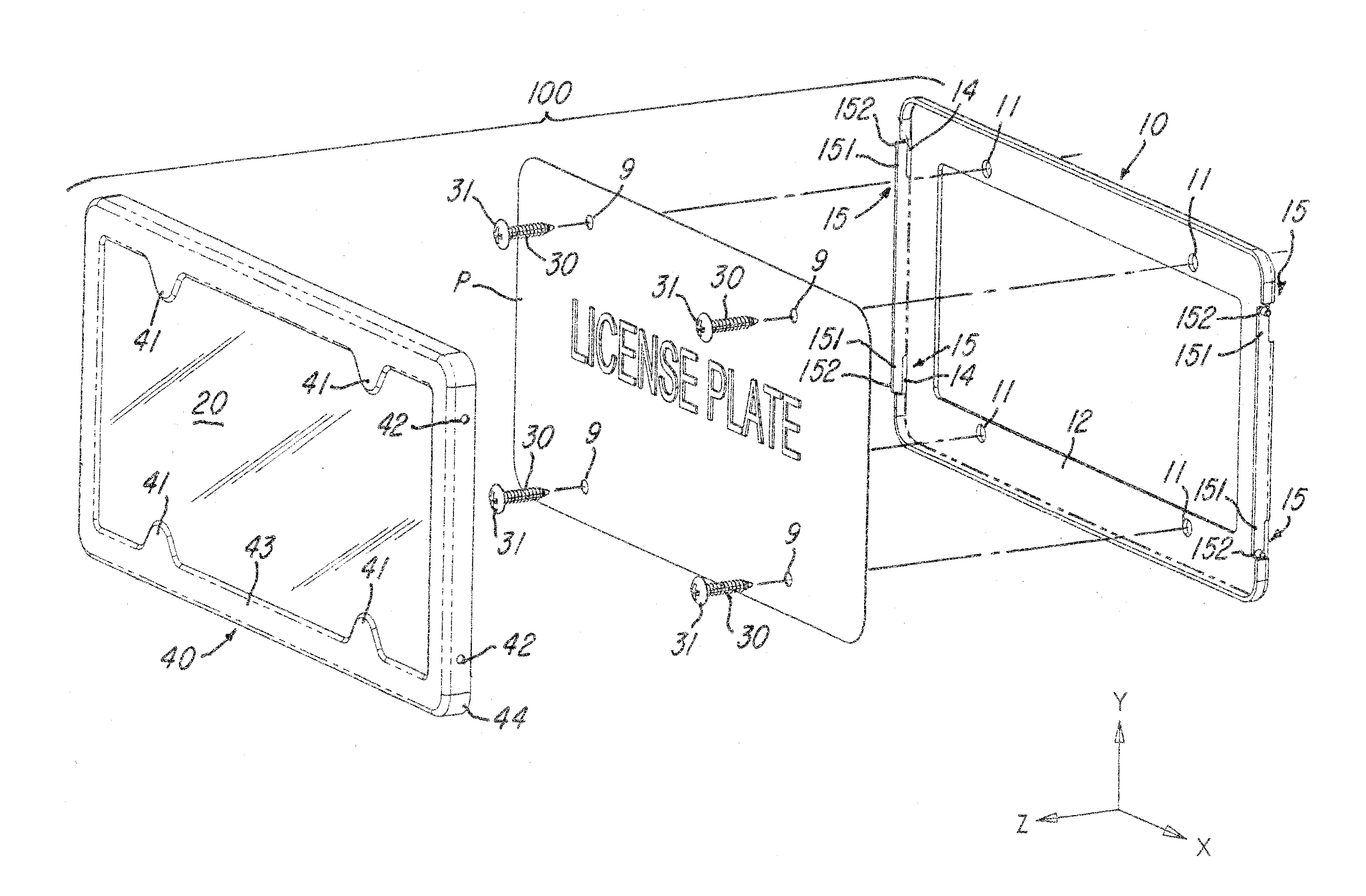
[0010]The license plate holder preferably includes a transparent plate disposed between the rear frame and the frame cover. The fastener may extend through the transparent plate or optionally the plate may be secured in place by the frame cover using adhesive or adhesive backed tape. The transparent plate may have at least one fastener head relief region to allow the transparent plate to fit over the fastener heads. Alternatively, this region of the transparent plate may be removed to allow access to the fastener heads after the frame cover is removed. Alternatively, the depth of the frame may be increased to provide additional clearance for fasteners without providing a relief in the transparent cover.
[0012]It is an object of the invention to provide a semi-secure license plate holder that can attach in a standard fashion to an automobile yet cover the fastener heads to improve the aesthetics and decrease the ease of license plate theft.
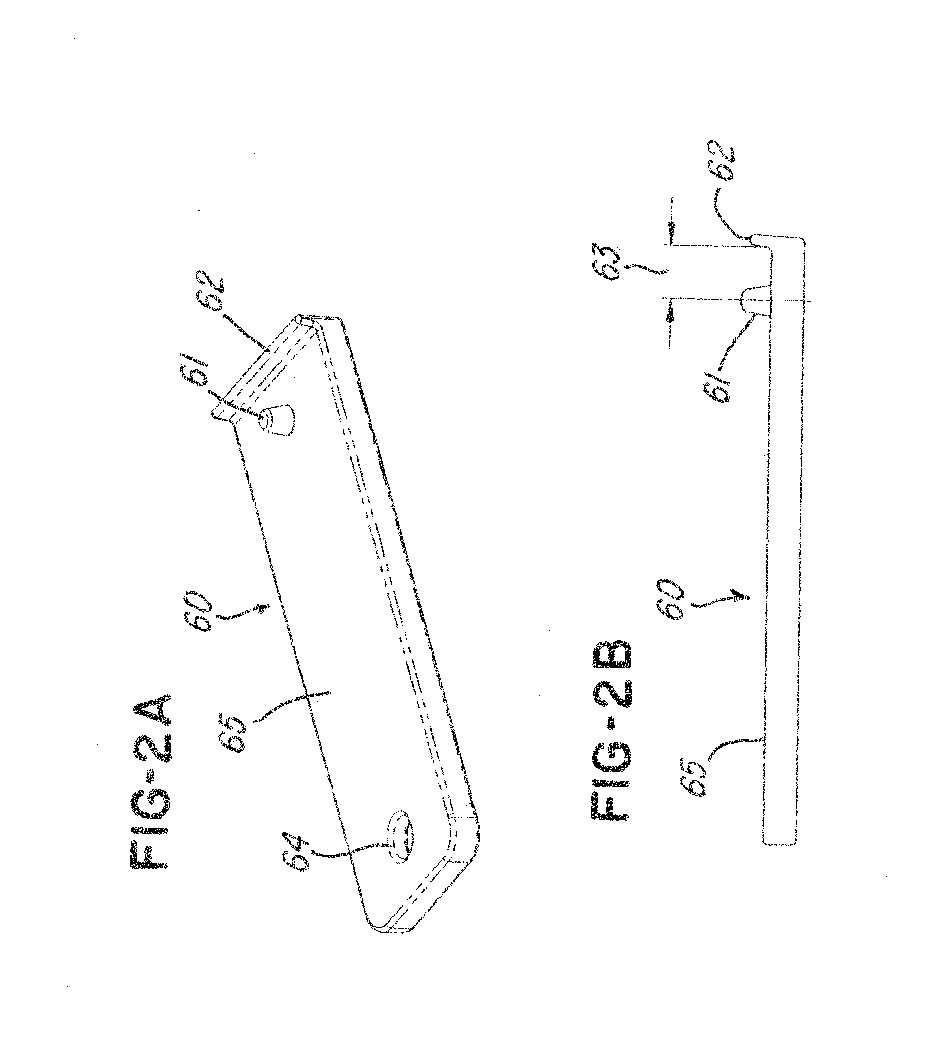
[0017]In still another aspect, one embodiment of the invention provides a frame for framing a license plate, the frame comprising a frame member having a cover face that becomes generally opposed to a front surface of the license plate when the cover is mounted on the vehicle, the cover face having a plurality of screw head covers that cover a plurality of screws so that at least one of visibility or accessibility of the screws is reduced.

Problems solved by technology

In either case the proposed license plate holder is likely too complicated for the average automobile owner.
Non-locking license plate holders such as that disclosed in U.S. Pat. No. 4,730,404 dated Mar. 15, 1988 are simpler but not aesthetically pleasing to some, nor do they require any tool or key for the removal of the license plate.

Method used


Image

  • Semi-locking license plate holder
  • Semi-locking license plate holder
  • Semi-locking license plate holder

Examples


Embodiment Construction

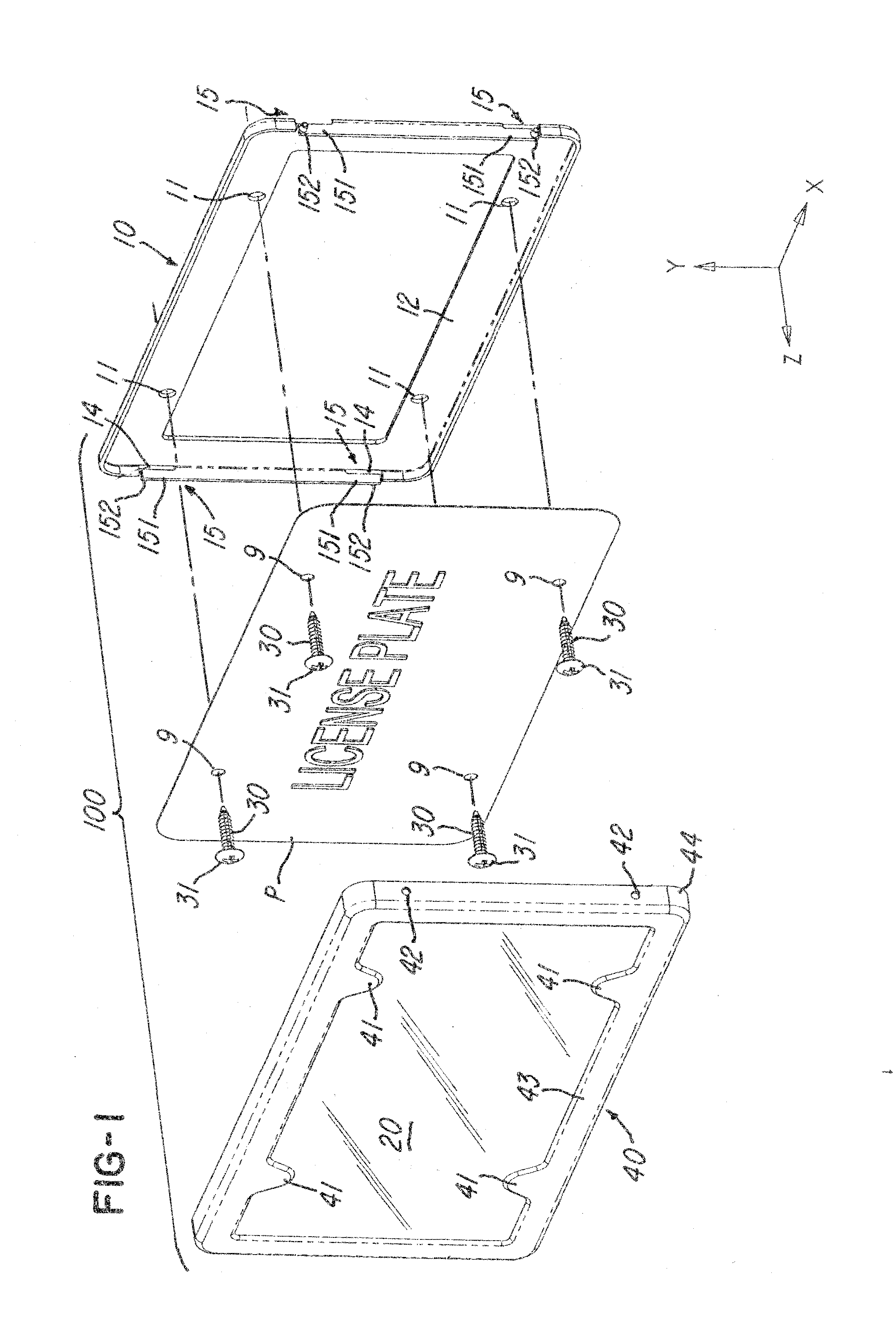
[0024]FIG. 1 shows a semi-locking license plate holder 100 having a rear frame 10, a license plate or frame cover 40 and an optional transparent plate 20.

[0025]The rear frame 10 includes at least one and preferably at least two fastener attachment points or apertures 11 that extend through a rear frame face 12 and an auto frame face (not shown). These attach points are used in conjunction with any fastener known in the art to attach the rear frame 10 to an automobile with the rear frame face 12 facing away from the automobile.

[0026]The rear frame 10 preferably includes a rear frame side edge 18. The rear frame side edge 18 preferably extends generally perpendicular from the rear frame face 12 and preferably extends away from the automobile. The rear frame side edge 18 may extend all the way around the rear frame 10 as shown in FIG. 1 or alternatively extend around only a portion of the rear frame 10.

[0027]The rear frame 10 further includes at least one assembly mechanism 15, prefera...


PUM


Abstract

A semi-locking license plate holder for an automobile including a rear frame, a frame cover and optionally a transparent plate. The rear frame has at least one fastener attach point for insertion of at least one fastener such that the fastener head abuts the rear frame securing it to the automobile. The frame further includes an assembly mechanism having at least one pin arm. The pin arm has at least one pin for attachment to the frame cover. The frame cover has at least one pin hole designed to align with at least one pin on the pin arm such that the pins may be inserted into the pin hole or holes. The frame cover has at least one fastener head cover for covering at least one and preferably all of the fastener heads such that the fastener heads cannot be used to remove the license plate without first removing the frame cover.

Description

CROSS-REFERENCE TO RELATED APPLICATIONS[0001]This patent application is related to provisional patent application Ser. No. 60 / 854,360, filed Oct. 26, 2006, to which Applicants claim the benefit of the earlier filing date. That application is incorporated herein by reference and made a part hereof.[0002]This patent application is also related to design patent application entitled “SEMI-LOCKING LICENSE PLATE HOLDER,” Ser. No. ______, filed concurrently herewith, and which is hereby incorporated by referenceBACKGROUND OF THE INVENTION[0003]1. Field of the Invention[0004]The invention relates to a license plate holder for securing a license plate to a vehicle.[0005]2. Description of the Related Art[0006]There are many examples of license plate holders in the prior art. Those with locking features such as U.S. Pat. No. 6,481,126 dated Nov. 19, 2002 are quite elaborate with a plurality of parts and moving parts. U.S. Pat. No. 4,903,422 dated Feb. 27, 1990 has fewer parts, provided you are...

Claims


Application Information

Patent Timeline
IPC IPC(8): B60R13/10G09F7/06
CPCB60R13/10Y10T70/5982
Inventor GRAHAM, MARK ALANOSBORNE, STEPHEN LEE
Owner REAL CARBON FIBER LLC D B A ZERO 261 DESIGN GRP
Learn More