Gas turbine engine assembly and methods of assembling same

a technology of gas turbine engines and assembly methods, which is applied in the direction of machines/engines, vessel construction, marine propulsion, etc., can solve the problems of overall and achieve the effect of increasing the overall weight, design complexity and/or manufacturing costs of such engines

Inactive Publication Date: 2008-05-01
GENERAL ELECTRIC CO
View PDF19 Cites 95 Cited by
  • Summary
  • Abstract
  • Description
  • Claims
  • Application Information

AI Technical Summary

Problems solved by technology

However, the overall weight, design complexity and / or manufacturing costs of such an engine are increased.

Method used


Image

  • Gas turbine engine assembly and methods of assembling same
  • Gas turbine engine assembly and methods of assembling same
  • Gas turbine engine assembly and methods of assembling same

Examples


Embodiment Construction

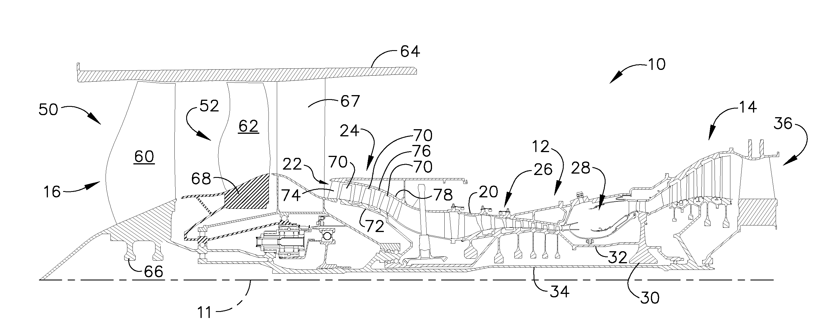
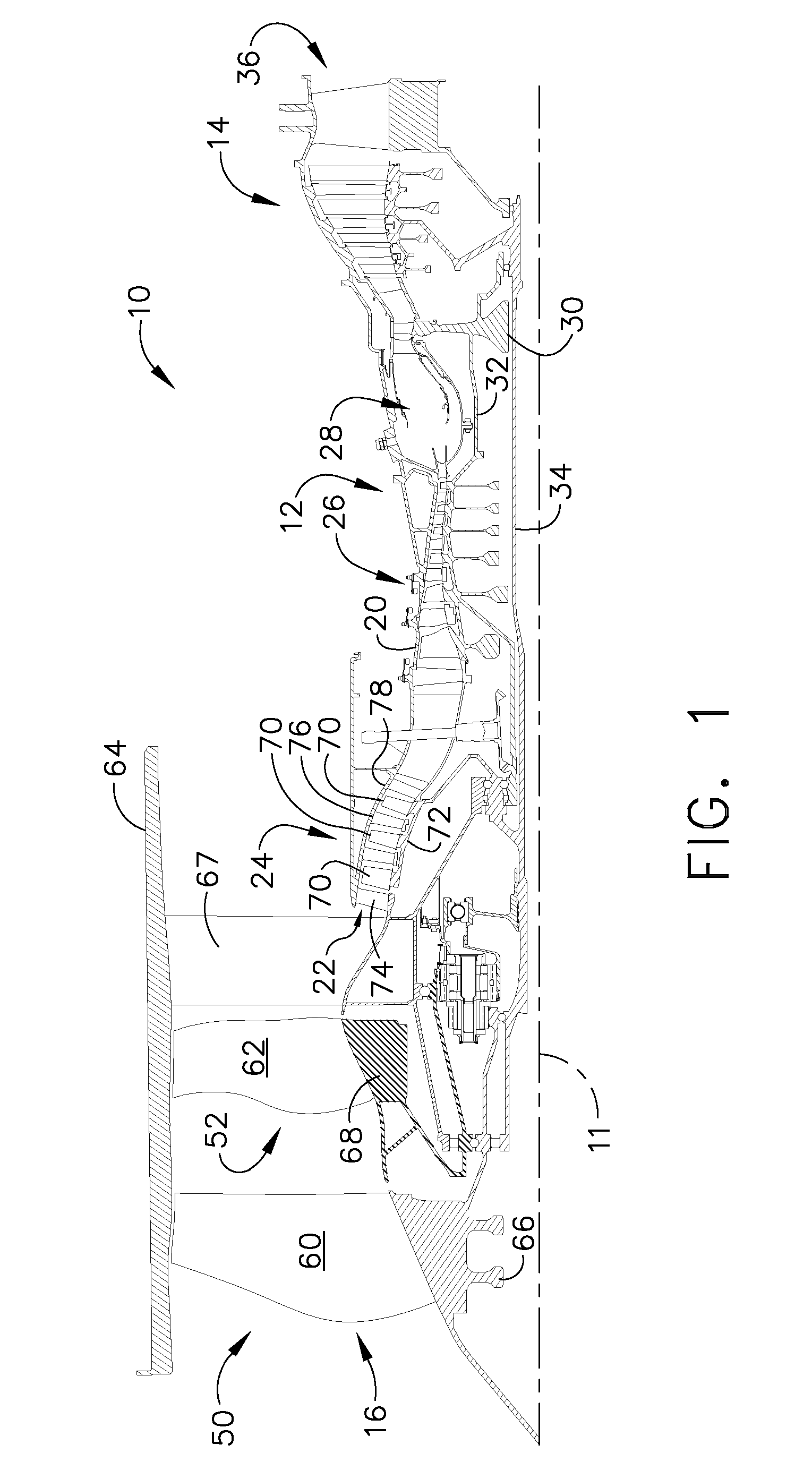
[0012]FIG. 1 is a cross-sectional view of a portion of an exemplary turbine engine assembly 10 having a longitudinal axis 11. In the exemplary embodiment, turbine engine assembly 10 includes a core gas turbine engine 12, a low-pressure turbine 14 that is disposed axially downstream from core gas turbine engine 12, and a counter-rotating fan assembly 16 that is disposed axially upstream from core gas turbine engine 12.

[0013]Core gas turbine engine 12 includes an outer casing 20 that defines an annular core engine inlet 22. Casing 20 surrounds a low-pressure booster compressor 24 that is utilized to increase an operating pressure of the inlet air to a first pressure level. A high-pressure, multi-stage, axial-flow compressor 26 receives pressurized air from booster compressor 24 and further increases the pressure of the air to a second, higher operating pressure. The high-pressure air is channeled to a combustor 28 and is mixed with fuel. The fuel-air mixture is ignited to raise the te...


PUM


Abstract

A method for assembling a gas turbine engine includes coupling a low-pressure turbine to a core turbine engine, coupling a counter-rotating fan assembly including a forward fan assembly and an axially aft fan assembly to the low-pressure turbine such that the forward fan assembly rotates in a first direction and the aft fan assembly rotates in an opposite second direction, and coupling a booster compressor directly to the low-pressure turbine such that the booster compressor rotates in the first direction.

Description

BACKGROUND OF THE INVENTION[0001]This invention relates generally to gas turbine engines, and more specifically to gas turbine engine assemblies that each include a booster compressor coupled to a low-pressure turbine and methods of assembling the same.[0002]At least some known gas turbine engines include a fan, a core engine, and a power turbine disposed downstream from the core engine. The core engine includes at least one compressor, a combustor, a high-pressure turbine and a low-pressure turbine disposed downstream from the core engine. More specifically, the compressor and high-pressure turbine are coupled through a shaft to define a high-pressure rotor assembly. Air entering the core engine is mixed with fuel and ignited to form a high energy gas stream. The high energy gas stream flows through the high-pressure turbine to rotatably drive the high-pressure turbine such that the shaft, in turn, rotatably drives the compressor.[0003]The gas stream expands as it flows through the...

Claims


Application Information

Patent Timeline
Patent Type & Authority Applications(United States)
IPC IPC(8): F02K3/02
CPCF01D15/12F05D2260/40311Y02T50/671F02K3/072Y02T50/60
Inventor ORLANDO, ROBERT JOSEPHMONIZ, THOMAS ORY
Owner GENERAL ELECTRIC CO
Why Eureka
Try Eureka