PCV valve

a valve and valve body technology, applied in the direction of crankcase ventillation, combustion engines, machines/engines, etc., can solve the problems of overheating in the electric heater, abnormal power application, and unclear position of the valve case, so as to effectively prevent the freezing of at least a valve elemen

Inactive Publication Date: 2008-05-01
AISAN IND CO LTD
View PDF8 Cites 42 Cited by
  • Summary
  • Abstract
  • Description
  • Claims
  • Application Information

AI Technical Summary

Benefits of technology

[0008]The present invention has been made in view of the above circumstances and has an object to provide a PCV valve capable of effectively preventing freezing of at least a valve element.

Problems solved by technology

However, in the device disclosed in JP '313, it is unclear about the position of the valve case in which the electric heater is placed.
Accordingly, the problem is the placement of the electric heater to heat the valve element and the valve seat provided in the valve chamber and associated parts with high efficiency.
On the other hand, in the device disclosed in JP '313, the occurrence of an abnormality of power application, in which power is continuously applied to the electric heater or an overcurrent flows through the electric heater due to a trouble of the controller or the like, is conceivable.
In this case, there is a probability of overheating in the electric heater in addition to power application loss in the electric heater.

Method used


Image

  • PCV valve
  • PCV valve
  • PCV valve

Examples


first embodiment

[0037]A detailed description of a first embodiment of a PCV valve of the present will now be given referring to the accompanying drawings.

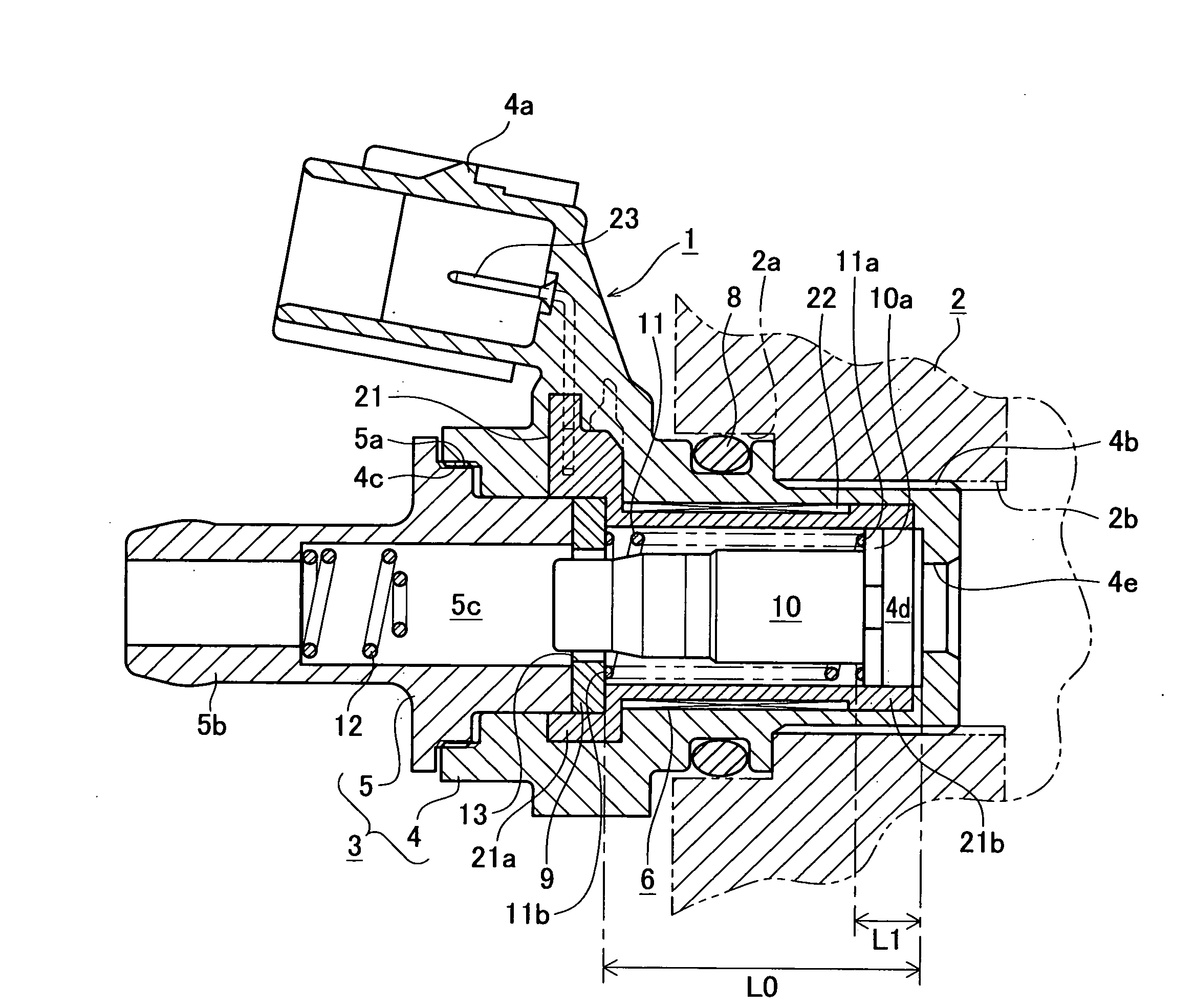
[0038]FIG. 1 is a sectional view of a PCV valve 1 of the present embodiment mounted on an engine main body 2. As it is well known, the PCV valve 1 is provided in a blow-by gas returning device to return blow-by gas, leaked from an engine combustion chamber to a crankcase, to an engine intake system, thereby preventing discharge of the blow-by gas into the atmosphere. As shown in FIG. 1, the PCV valve 1 has a resin housing 3 having a hollow shape. The housing 3 is formed with mutually assembled main housing 4 and sub housing 5.

[0039]The main housing 4 includes a connector 4a formed in its upper part, an assembly of an electric heater 6 integrally provided inside, and a seal ring 8 attached to an outer periphery of the main housing 4. The sub housing 5 is assembled with the main housing 4 by threadedly engaging external screw-threads 5a formed on th...

second embodiment

[0053]Next, a second embodiment of the PCV valve of the present invention will be described in detail with reference to the accompanying drawings.

[0054]Note that in the following second and third embodiments, components identical to those in the first embodiment will be given the same reference numerals and the explanations thereof will be omitted. The following explanation is made with a focus on the differences from the first embodiment.

[0055]In a PCV valve 31 of the present embodiment, the size of the electric heater 6 in the valve chamber 4d is different from that in the first embodiment. FIG. 7 is a sectional view of the PCV valve 31 of the present embodiment. In the present embodiment, the length of the bobbin 21 of the electric heater 6 is somewhat shorter than that in the first embodiment, relative to the length of the valve chamber 4d in the axial direction. That is, in FIG. 7, assuming that the entire area of the inner peripheral surface of the valve chamber 4d is “L0”, th...

third embodiment

[0057]Next, a third embodiment of the PCV valve of the present invention will be described in detail with reference to the accompanying drawings.

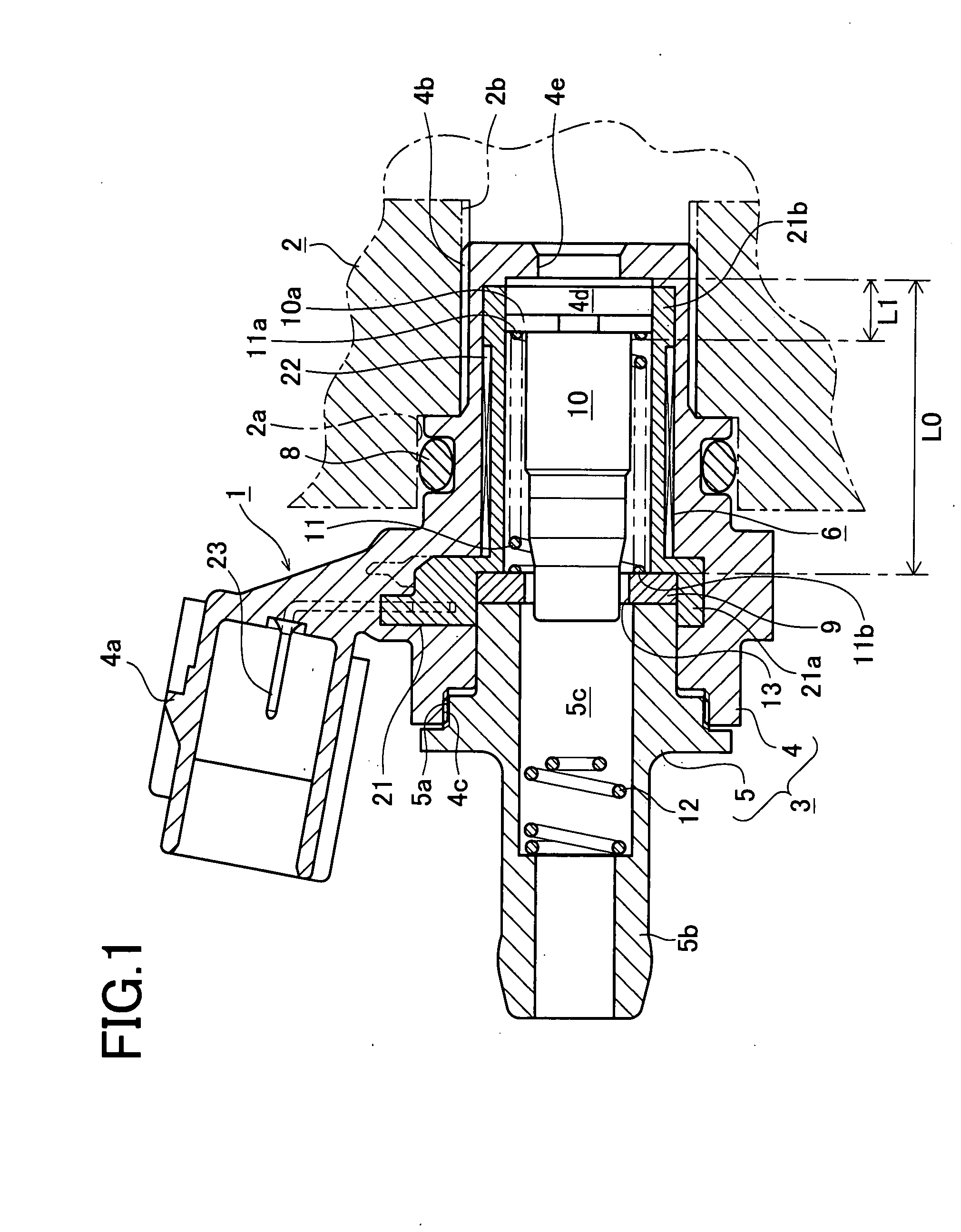
[0058]In the PCV valve of the present embodiment, the difference from the above-described embodiments is the relation among the valve seat 9, the valve element 10, and the compression spring 11. FIG. 8 is a partially cutaway side view showing the relation among the valve seat 9, the valve element 10, and the compression spring 11. In the present embodiment, the difference from the first embodiment is that the second end 11b of the compression spring 11 is engaged with a hook 9a formed in the wall of the valve seat 9, and the first end 11a of the compression spring 11 is engaged with a hook 10b formed in the flange 10a of the valve element 10.

[0059]According to the present embodiment, the second end 11b of the compression spring 11 is engaged with the valve seat 9, and the first end 11a of the compression spring 11 is engaged with the flange...


PUM


Abstract

A PCV valve include a housing which internally has a valve chamber including an entrance at one end and an exit at the other end in an axial direction of the valve chamber. In the valve chamber, a valve element which is axially movable and a spring which urges the valve element toward the entrance are provided. An electric heater is provided in the housing. The valve element includes an end which is movable close to the entrance. The electric heater is arranged in such a manner as to surround the valve chamber from the exit to the end of the valve element closer to the entrance. The electric heater includes a cylindrical bobbin made of a high heat-conductive material and a coil wound on the outer periphery of the bobbin. The bobbin has an inner peripheral surface forming a large part of an inner peripheral surface of the valve chamber.

Description

BACKGROUND OF THE INVENTION[0001]1. Field of the Invention[0002]The present invention relates to a blow-by gas returning device to return blow-by gas, leaked from an engine combustion chamber to a crankcase, to an engine intake system, thereby preventing discharge of the blow-by gas into the atmosphere, and to a PCV (Positive Crankcase Ventilation) valve provided in the device.[0003]2. Description of Related Art[0004]Conventionally, as this type of technique, devices disclosed in Japanese Published Unexamined Utility Model Applications Nos. 61-122313(1986), 4-117129(1992) and 60-98709(1985) are known. JP '313 discloses a structure in which a valve case includes a valve chamber and an electric heater is provided on the outer periphery of the valve case.[0005]Further, JP '129 discloses a structure in which a PCV valve is provided in a blow-by system connected to an engine intake system. An electric heater is incorporated in the PCV valve and a temperature sensor for detecting ambient ...

Claims


Application Information

Patent Timeline
Patent Type & Authority Applications(United States)
IPC IPC(8): F02B25/00
CPCF01M13/0011F02B25/00F01M2013/0027
Inventor SUZUKI, KOICHITATEISHI, MAMORUISHIDA, KATSUMIASANUMA, HIROSHIKONOHARA, HIROKAZUIDE, HIDETO
Owner AISAN IND CO LTD
Why Eureka
Try Eureka