Pneumatic Tire

a pneumatic tire and rib end technology, applied in the field of pneumatic tires, can solve the problems of uneven wear produced locally in the circumferential direction of the rib end circumferential direction, inability to achieve satisfactory results, and prone to vary in so as to reduce the variation in rigidity in the circumferential direction of the rib end circumference, improve the rigidity of the rib end, and improve the road holding capacity

Active Publication Date: 2008-05-01
TOYO TIRE & RUBBER CO LTD
View PDF16 Cites 17 Cited by
  • Summary
  • Abstract
  • Description
  • Claims
  • Application Information

AI Technical Summary

Benefits of technology

[0011]It is an object of the present invention to provide a pneumatic tire which has tread ribs whose rigidity is prevented from varying during operation of the tire and which has improved road holding capability to thereby improve the wear resistance of the rib pattern of the tire, whereby eruption of uneven wear such as river wear is especially suppressed.
[0014]In this structure, the closed sipes are spaced circumferentially from each other among the ribs. The rigidity of the ribs within the tread surface can be made uniform by setting the interval between the sipes to a small value. Thus, the road holding capability can be improved. Consequently, uniform wear can be achieved.
[0015]Uneven wear of the rib pattern is understood as follows. During operation, when shearing force or slipping force consisting mainly of lateral stress acts on the ribs, the ends of the ribs move more than the other portions within the tread surface, resulting in local wear. The local wear is extended circumferentially along the rib edges. The ribs according to the present invention reduce circumferential variations in rigidity because any block created by open sipes does not exist. Furthermore, the closed sipes improve the road holding capability of the ribs. Excessive motion within the tread surface is reduced. Consequently, uneven wear can be suppressed.
[0016]Furthermore, in the pneumatic tire according to the invention, the closed sipes are formed in regions of 20 to 30% of the actual width of the ribs. The ratio of the length of each closed sipe as measured circumferentially of the tire to the length as measured width of the tire (circumferential length / lateral length) is in a range of from 1 to 2. Thus, circumferential variations in rigidity within the tread surface are suppressed. As a result, the road holding capability can be made uniform. In addition, the road holding capability of the ribs is improved, because the closed sipes are disposed in the plural ribs. Where the closed sipes are formed in regions exceeding 30% of the actual width of the ribs, the closed sipes open axially of the tire. This will form a starting point of wear. More preferably, the circumferential interval between the closed sipes in the ribs is set to 3 to 4 times the length of the sipes. Consequently, the spaces between the sipes act to mitigate deformation of the ribs, as well as the regions where the closed sipes are disposed. This reduces and makes uniform the contact pressure of the ribs on the road in front and behind the closed sipes circumferentially. In consequence, the wear resistance is improved.
[0018]Further, in the pneumatic tire according to the invention, the closed sipes are successively offset circumferentially of the tire in the direction in which the outermost-layer belt cords of the tire extend in one repeating unit of the periodic pattern of the closed sipes. The line connecting both ends of each sipe intersects the direction in which the outermost-layer belt cords extend. Therefore, when air is introduced into the tire to create an inside pressure, the spacing between the belt cords tends to spread. Because of this action, the closed sipes are suppressed from being opened. This secures rigidity of the ribs. Furthermore, eruption of cracks can be suppressed.

Problems solved by technology

Especially, there has been the problem that river wear that is uneven wear produced locally in the circumferential direction of the rib ends is caused easily.
Satisfactory results cannot be obtained only if the short sipes are disposed.
However, the rigidity of the ribs tends to vary, and the road holding capability deteriorates.
This creates increased strain.
As a result, deformation easily occurs.
Wear starts from the location where the strain is produced, resulting in cracks.
Hence, there is the problem that uneven wear tends to be produced easily.

Method used


Image

  • Pneumatic Tire
  • Pneumatic Tire
  • Pneumatic Tire

Examples


examples

[0053]Specific examples of the present invention are described in detail below.

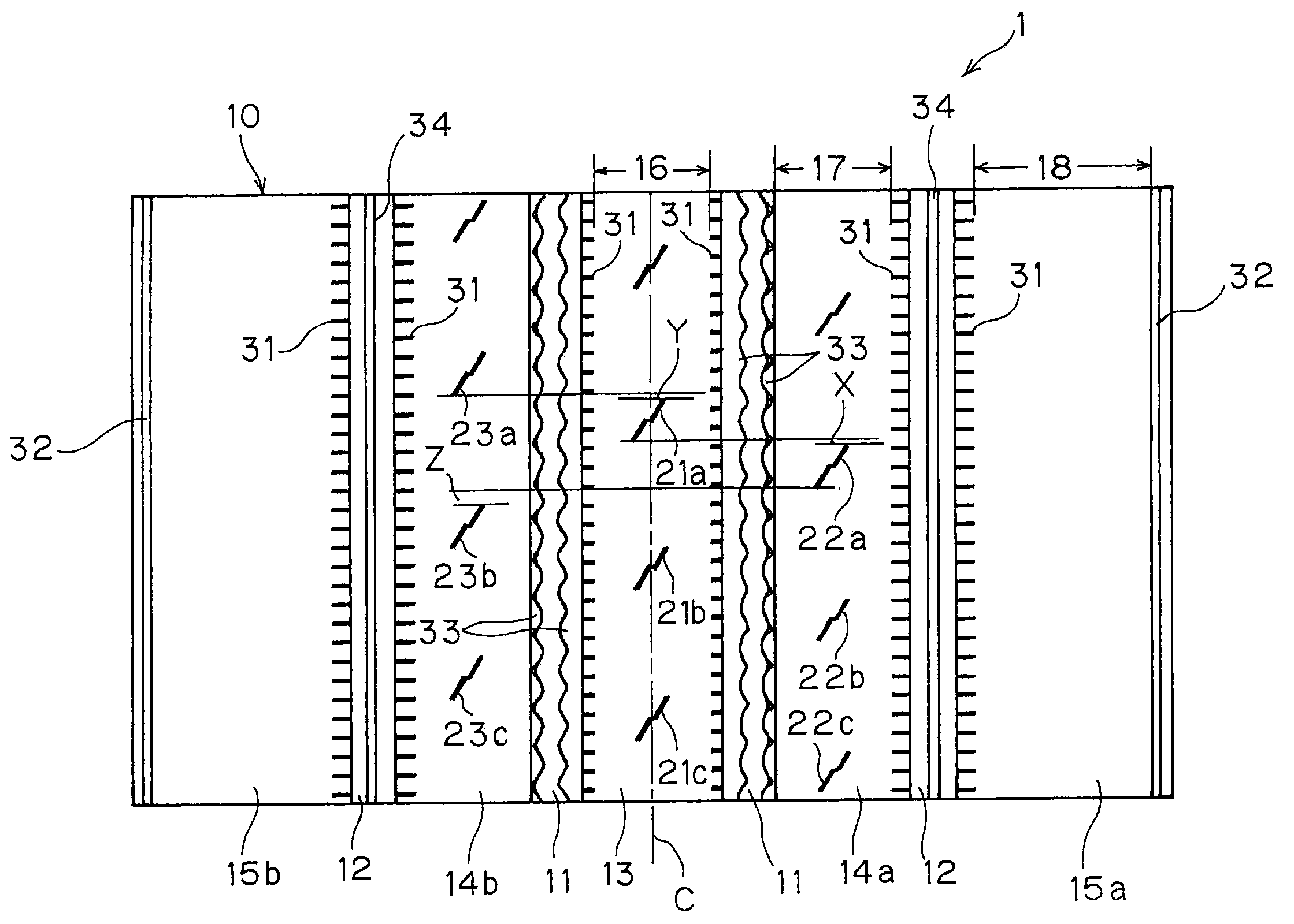
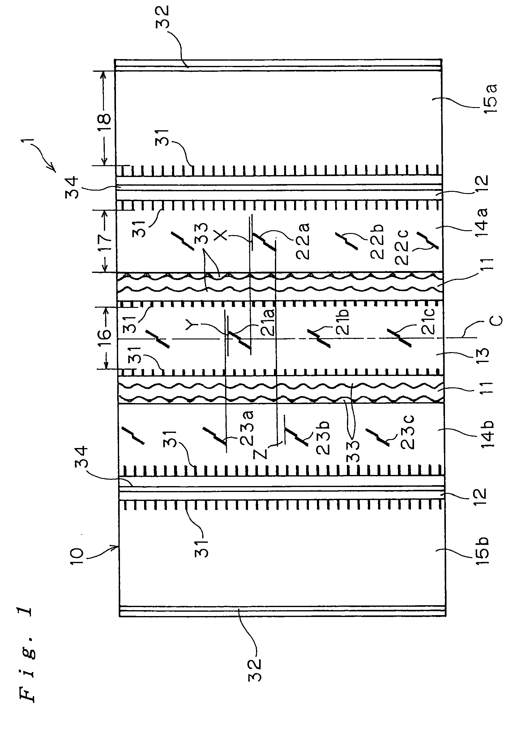
[0054]Tires according to the present invention were prototyped as examples of the invention. Each of these tires had a tread pattern shown in FIG. 1 and zigzag closed sipes shown in FIG. 3. A comparative example having the same tread pattern as the pattern of the examples of the invention was also prototyped. The specifications (including the dimensions of the closed sipes and their arrangement) of the comparative example were modified as listed in Table 1. These tires were evaluated in terms of performance.

[0055]Each tire was a radial tire having tire size 295 / 75R22.5. Steel cords of 3+8×0.22 mm were struck into the carcass plies at a density of 30 / 50 mm. Steel cords of 3×0.20+6×0.35 mm were struck into the belt plies from the innermost layer adjacent to the carcass layer to the third layer at a density of 25 / 50 mm. High-elongation steel cords of 1×5×0.35 mm were struck into the belts in the outermost la...


PUM


Abstract

A pneumatic tire having improved wear resistance, especially improved uneven wear resistance (such as river wear), is offered. The tire that is a rib-pattern tire has five ribs extending circumferentially of the tire. The ribs include a center rib and intermediate ribs located on the opposite sides of the center rib that is located on the equator line of the tire. Closed sipes are formed at least in the center rib and in the intermediate ribs. Each sipe is located in the lateral center of the corresponding rib. Both ends of each sipe terminate within the corresponding rib. The closed sipes are successively offset circumferentially among the ribs and arranged in a periodic pattern on the outer surface of the tire. The closed sipes in the ribs are so arranged that when they are optically projected onto the equator line of the tire, the sipes do not overlap circumferentially of the tire among the ribs.

Description

BACKGROUND OF THE INVENTION[0001]1. Field of the Invention[0002]The present invention relates to a pneumatic tire having a rib pattern and, more particularly, to a pneumatic tire using ribs having improved wear resistance. Still particularly, the invention relates to a pneumatic tire designed to prevent uneven wear.[0003]2. Description of the Related Art[0004]Main types of uneven wear of a pneumatic tire having a rib pattern are (1) step wear starting from the end of the tire in the direction of the axis of rotation of the tire, the end touching the road surface, and (2) river wear produced in rib ends on both sides of each circumferential groove. Especially, there has been the problem that river wear that is uneven wear produced locally in the circumferential direction of the rib ends is caused easily.[0005]In the past, the above-described step wear, or one kind of uneven wear, has been effectively prevented by forming thin circumferential grooves near the road-contacting shoulder ...

Claims


Application Information

Patent Timeline
Patent Type & Authority Applications(United States)
IPC IPC(8): B60C11/04
CPCB60C11/042B60C11/12B60C11/047Y10S152/901B60C11/045B60C2011/0388Y10S152/03B60C2011/1254
Inventor OHARA, MASAAKI
Owner TOYO TIRE & RUBBER CO LTD
Why Eureka
Try Eureka