

MEMS bubble generator for large stable vapor bubbles
- Summary
- Abstract
- Description
- Claims
- Application Information
AI Technical Summary
Benefits of technology
Problems solved by technology
Method used
Image

Examples
Embodiment Construction
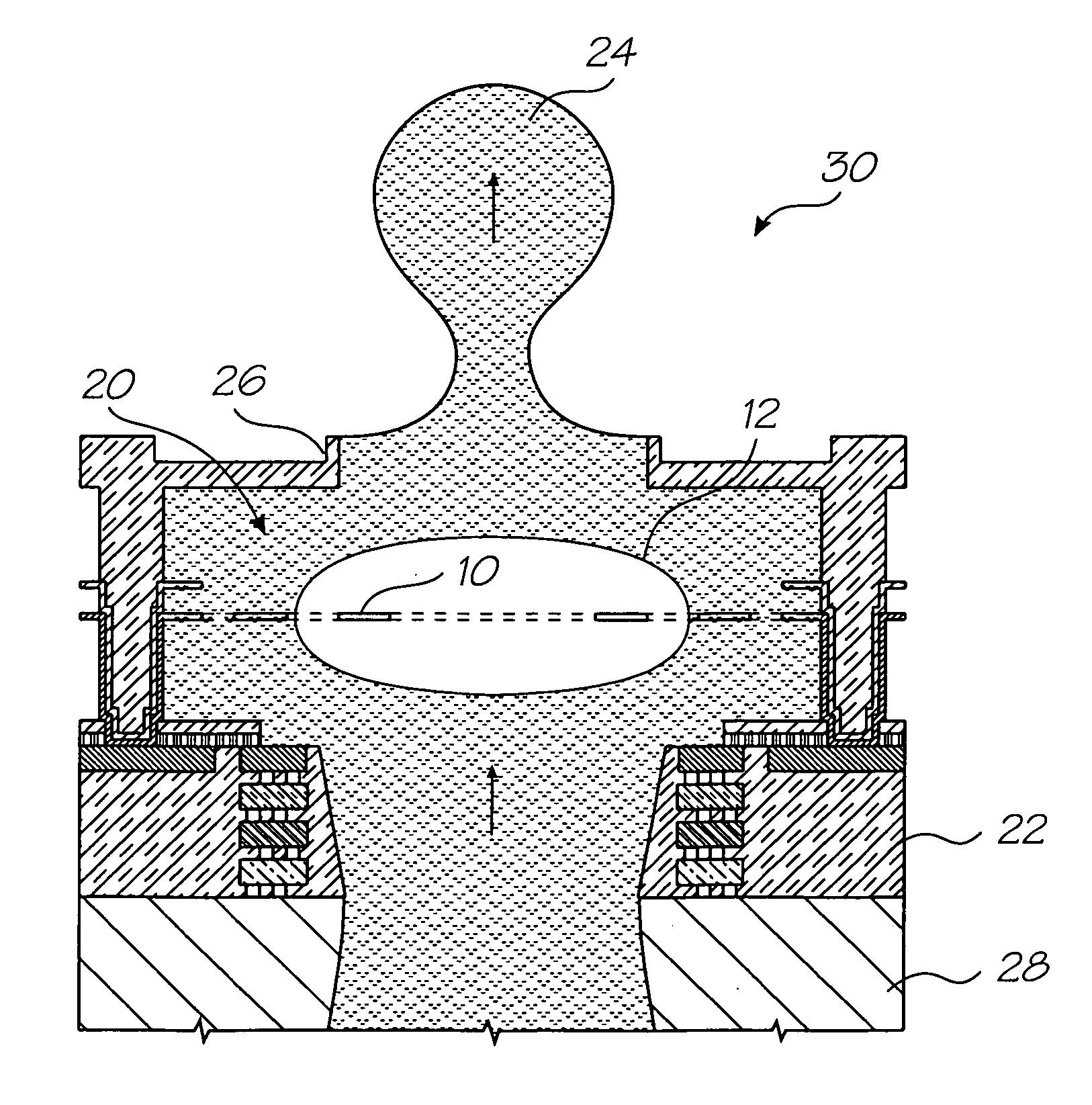
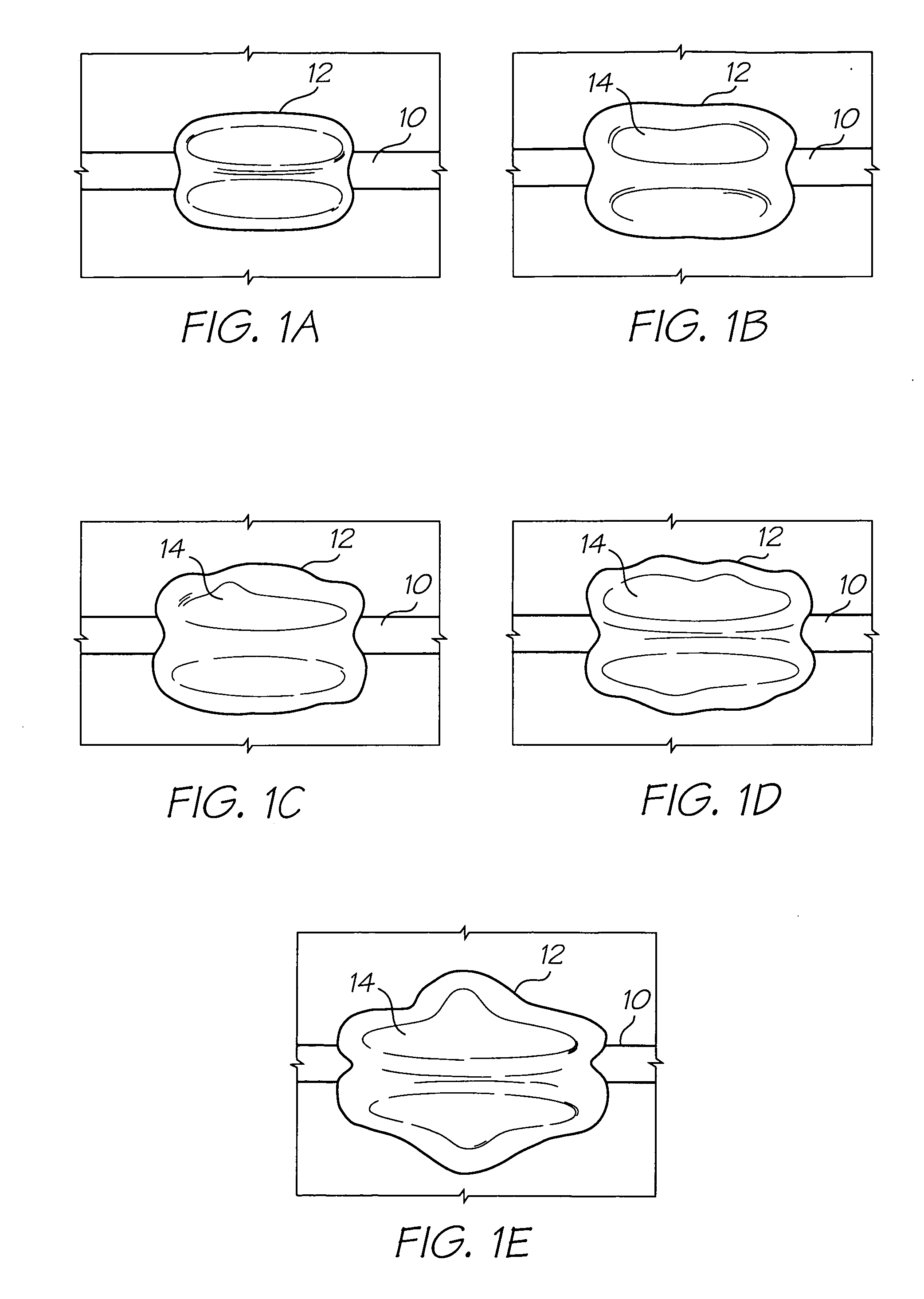
[0038]In a MEMS fluid pump, large, stable and repeatable bubbles are desirable for efficient and reliable operation. To analyse the mechanisms that influence bubble nucleation and growth, it is necessary to consider the spatial uniformity of the heater's temperature profile and then consider the time evolution of the profile. Finite element thermal models of heaters in liquid can be used to show that the heating rate of the heater strongly influences the spatial uniformity of temperature across the heater. This is because since different portions of the heater are heat-sunk to different degrees (the sides of the heater will be colder due to enhanced cooling by the liquid and the ends of the heater will be colder due to enhanced cooling by the contacts). At low powers, where the time scale for heating to the superheat limit is large with respect to the thermal time scales of the cooling mechanisms, the temperature profile of the heater will be strongly distorted by cooling at the bou...
PUM
| Property | Measurement | Unit |
|---|---|---|
| Power | aaaaa | aaaaa |
| Viscosity | aaaaa | aaaaa |
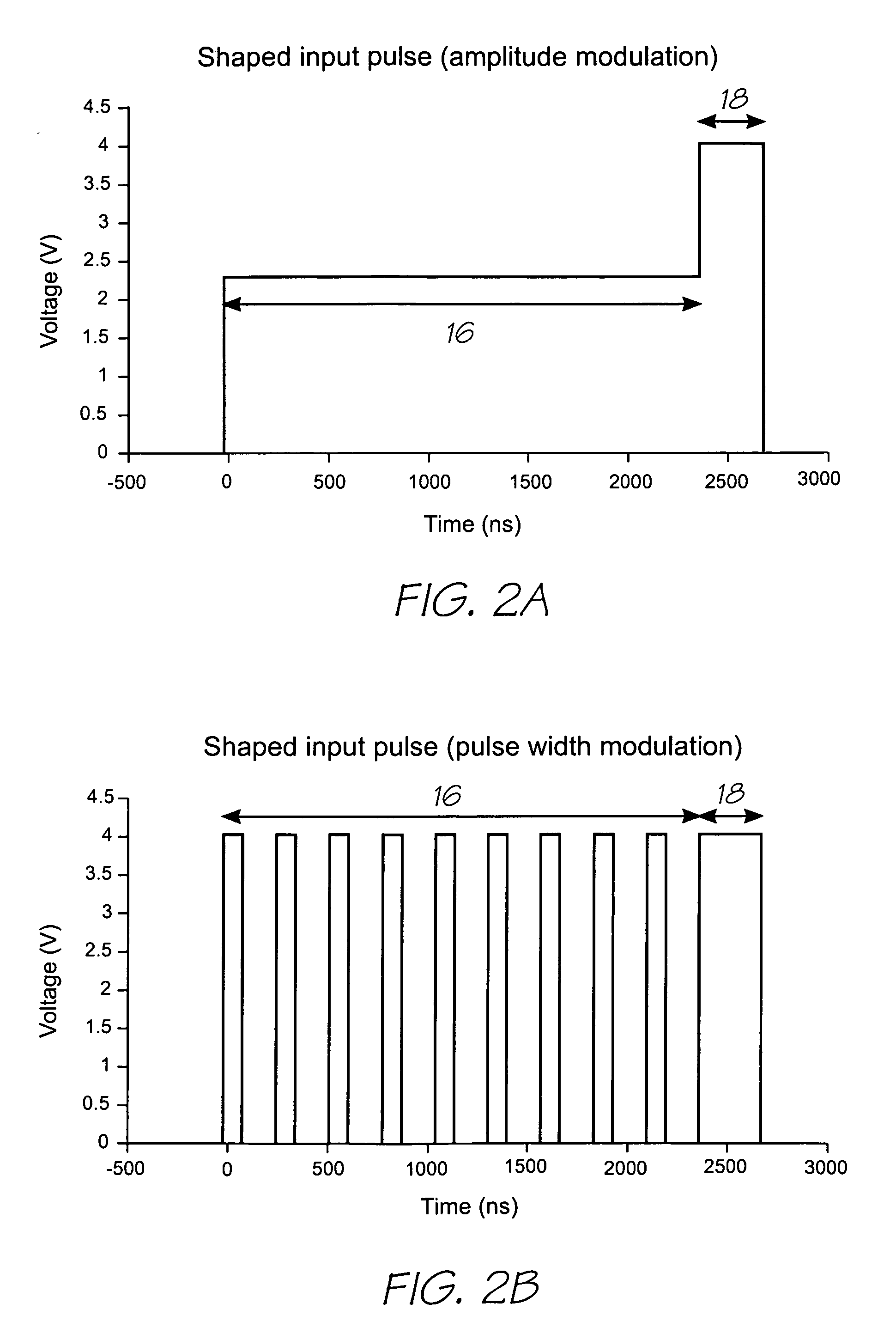
| Electric potential / voltage | aaaaa | aaaaa |
Abstract
Description
Claims
Application Information