Method and apparatus for microwave and millimeter-wave imaging

a microwave and millimeter-wave imaging and method technology, applied in the field of electronic systems and methods, can solve the problems of increasing cost, requiring a higher sensitivity receiver, and poor image contrast in indoor applications

Inactive Publication Date: 2008-05-01
BONTHRON ANDREW J +1
View PDF13 Cites 117 Cited by
  • Summary
  • Abstract
  • Description
  • Claims
  • Application Information

AI Technical Summary

Problems solved by technology

Passive sensors can have an advantage of not requiring transmit circuitry, but typically have poorer image contrast in indoor applications, and also typically require a higher sensitivity receiver which can add cost.
To increase the number of image pixels, reduce the size of image pixels, or provide higher image resolution, typically the size and cost of an imaging sensor is increased.
This can be detrimental to application and deployment.
This, however, typically adds cost and complexity to the sensor.
However, there exists a finite speed in which mechanical scanning can be performed, o

Method used


Image

  • Method and apparatus for microwave and millimeter-wave imaging
  • Method and apparatus for microwave and millimeter-wave imaging
  • Method and apparatus for microwave and millimeter-wave imaging

Examples


Embodiment Construction

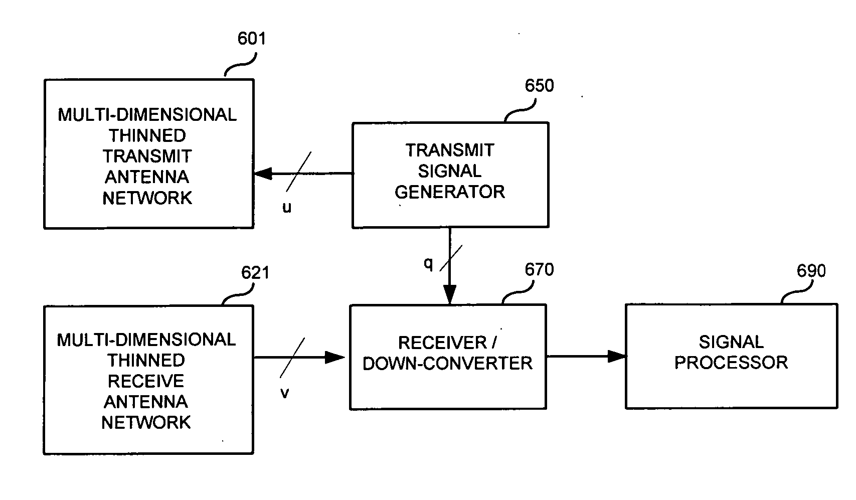
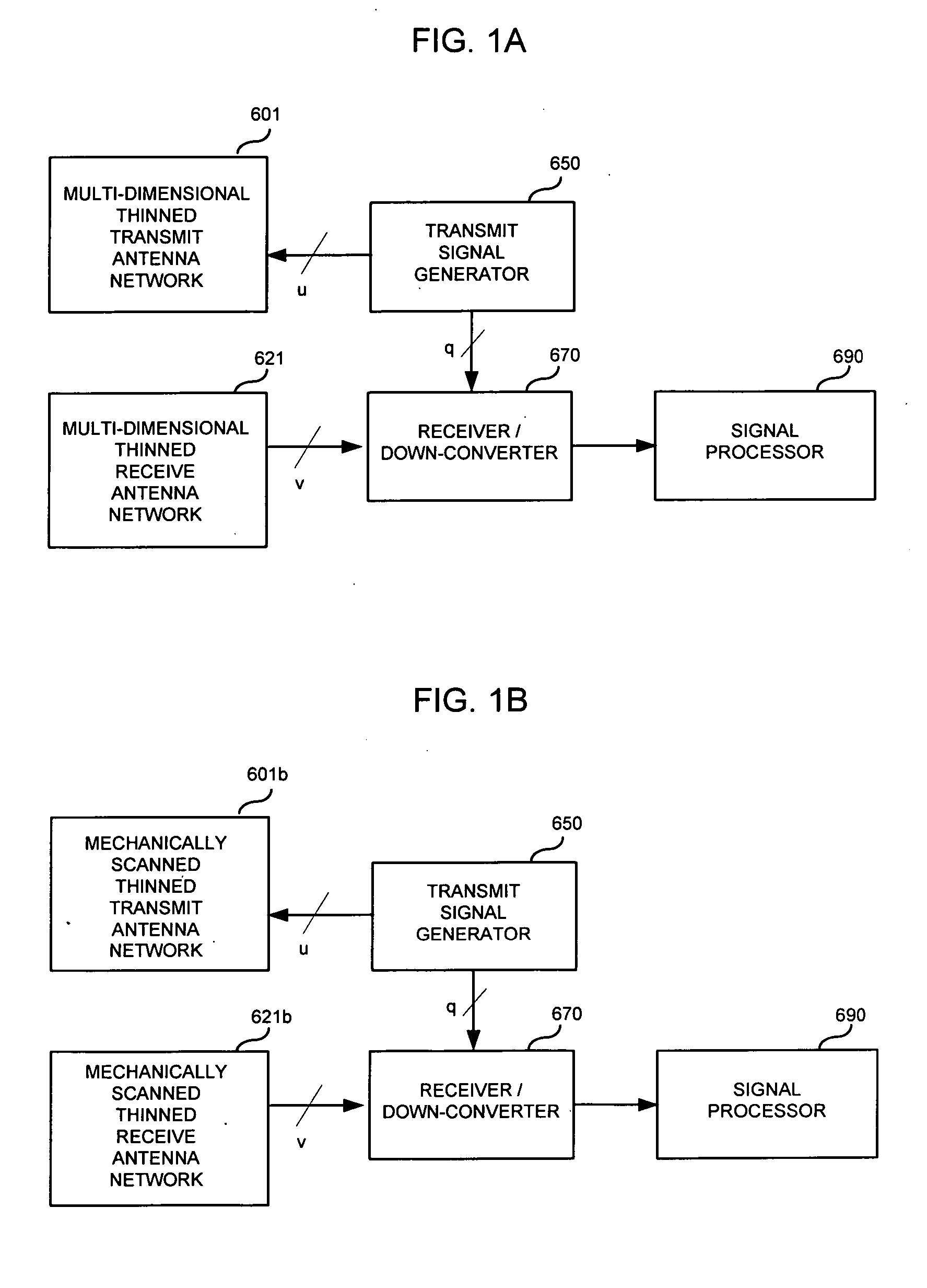
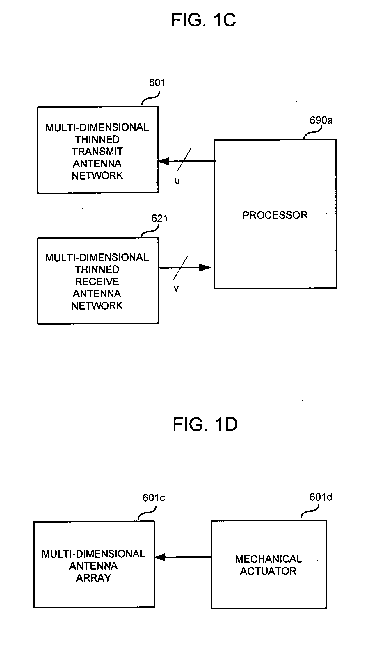
[0046] An imaging sensor arrangement is presented in FIG. 1A as one embodiment of aspects of the present invention. In this arrangement, the transmit signal generator 650 outputs u signals to a multi-dimensional thinned transmit antenna network 601 for electromagnetic transmission, where u is an integer greater than or equal to 1. A typical frequency of the transmitted signal from the multi-dimensional thinned transmit antenna network 601 can be within, but is not limited to, the frequency range of 1 GHz-1 THz, and can be a fixed frequency or be frequency modulated. The imaging sensor's total occupied transmit spectral bandwidth is dependent on the frequency modulation bandwidth, and can be wideband (WB) or ultra-wideband (UWB) in order to achieve adequate range resolution for some applications. A typical WB bandwidth value can be, but is not limited to, a value greater than 100 MHz. A typical UWB bandwidth value can be, but is not limited to, a value greater than 1 GHz. The reflect...


PUM


Abstract

An antennae system for a detector. The antennae system includes a two-dimensional electro-magnetic transmitter array that has an x number of transmitter elements, and a two-dimensional electro-magnetic receiver array that has a y number of receiver elements. The two-dimensional electro-magnetic transmitter and receiver arrays have a spatial relationship such that at least one subset of the two-dimensional electro-magnetic transmitter and receiver arrays forms a regular array of spatial displacements of z pairwise combinations of transmitter and receiver elements, where z is greater than the sum of x and y.

Description

CROSS-REFERENCE TO RELATED APPLICATIONS [0001] This application claims priority to Application No. 60 / 854,783 filed on Oct. 27, 2006.BACKGROUND OF THE INVENTION [0002] 1. Technical Field of the Invention [0003] The subject matter disclosed generally relates to the field of electronic systems and methods. More specifically, the subject matter disclosed relates to electronic arrangements that allow cost reduction and increased utility for microwave and millimeter-wave imaging applications. [0004] 2. Background of Related Art [0005] Imaging sensors utilizing electromagnetic signals in the millimeter-wave frequency spectrum have demonstrated the ability to detect objects obscured from sight such as handguns concealed underneath clothing and metal objects inside of bags, due to the ability of signals in this frequency range to penetrate clothing and various other materials. For this discussion, the term “millimeter-wave” includes the microwave spectrum and refers to frequencies in the ra...

Claims


Application Information

Patent Timeline
IPC IPC(8): H01Q3/00
CPCH01Q21/29H01Q21/061G01S7/024G01S13/89
Inventor BONTHRON, ANDREW J.JUSKOVIC, GERALD
Owner BONTHRON ANDREW J
Why Eureka
Try Eureka