
Full-range speaker device

a speaker device and full-range technology, applied in the direction of transducer details, electrical transducers, electrical apparatus, etc., can solve the problems of requiring amplifiers of much higher power, foregoing design, and not only expensiv

Inactive Publication Date: 2008-05-01
SUN CHENG YUAN
View PDF5 Cites 4 Cited by
  • Summary
  • Abstract
  • Description
  • Claims
  • Application Information

AI Technical Summary

Benefits of technology

[0004]The primary purpose of the present invention is to provide, a full-range speaker device that can economically deliver high-fidelity trebles. The major feature of the present invention lies in that the voice coil is sandwiched between two or more concentric bobbins. As such, out of the same back-and-forth movement of the bobbins, different ranges of sounds are produced through separate bobbins by the diaphragms attached to the bobbins, respectively. Crystal high-pitch sounds are therefore achieved by the present invention.

Problems solved by technology

The disadvantage of the foregoing design is as follows.
Therefore, to achieve high-fidelity sounds, conventionally multiple speakers each dedicated to a specific range of sounds are provided, which not only is costly but also requires an amplifier of much higher power.

Method used


Image

  • Full-range speaker device
  • Full-range speaker device
  • Full-range speaker device

Examples


Embodiment Construction

[0009]The following descriptions are exemplary embodiments only, and are not intended to limit the scope, applicability or configuration of the invention in any way. Rather, the following description provides a convenient illustration for implementing exemplary embodiments of the invention. Various changes to the described embodiments may be made in the function and arrangement of the elements described without departing from the scope of the invention as set forth in the appended claims.

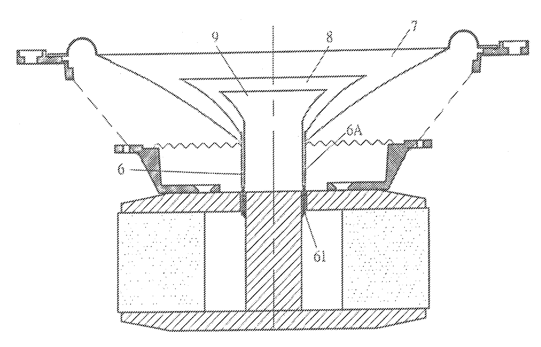
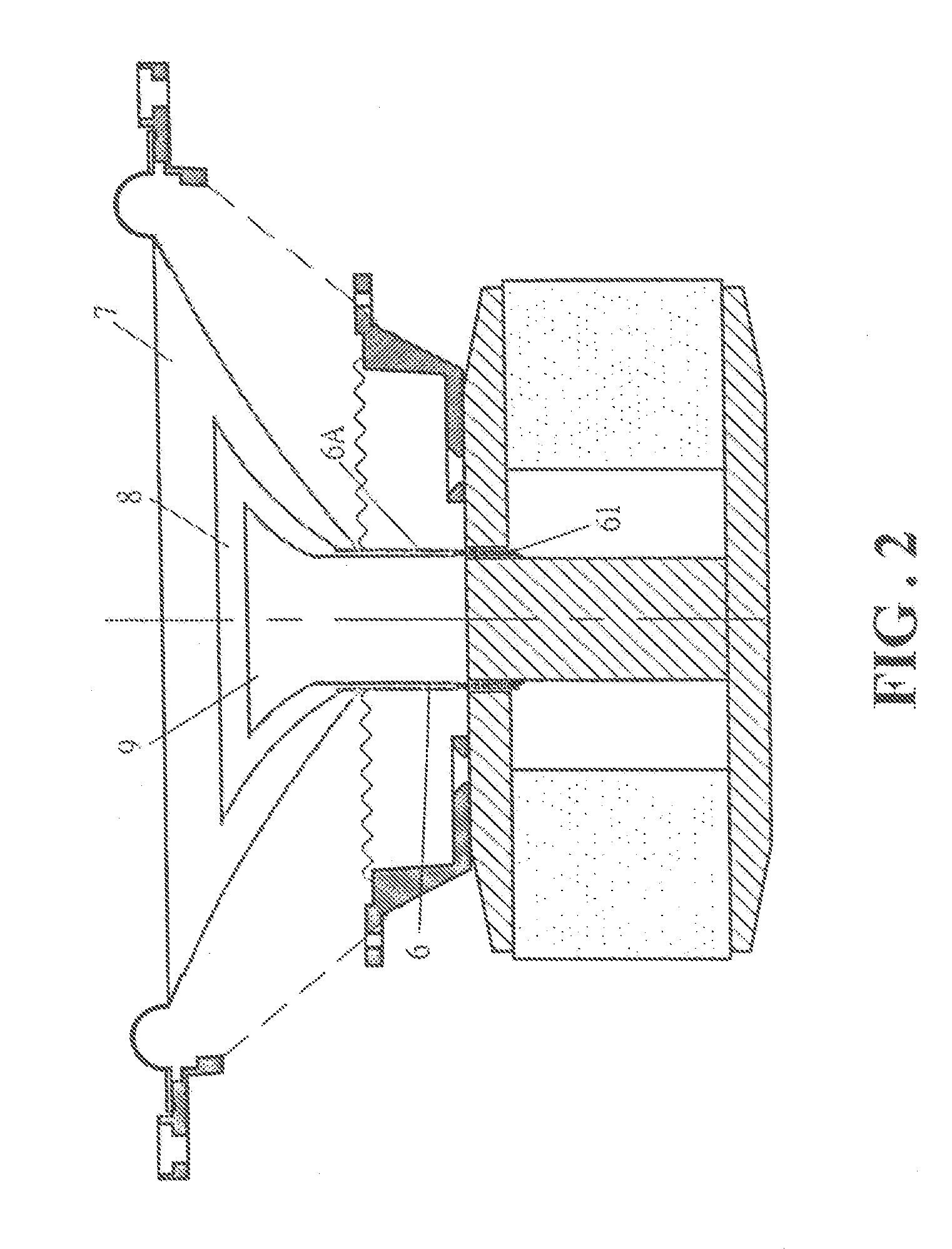
[0010]FIG. 2 is a schematic sectional view showing a full-range speaker device according to an embodiment of the present invention. The basic structure of the present invention is similar to the prior arts in that the circumference of a first bobbin 6 is wound by a voice coil 61. The major difference lies in that at least a concentric second bobbin 6A is configured around the voice coil 61, thereby housing the first bobbin 6 inside. A treble diaphragm 9 is attached to and positioned in the center of...


PUM


Abstract

A full-range speaker device is provided herein that can deliver high-fidelity trebles. The major feature of the present invention lies in that the voice coil is sandwiched between two or more concentric bobbins. As such, out of the same back-and-forth movement of the bobbins, different ranges of sounds are produced through separate bobbins by the diaphragms attached to the bobbins, respectively.

Description

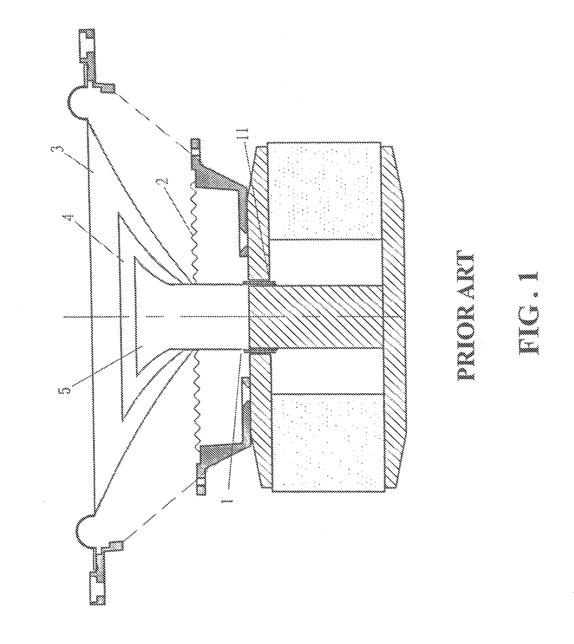
TECHNICAL FIELD OF THE INVENTION[0001]The present invention generally relates to full-range speakers or loudspeakers, and more particularly to a full-range having multiple bobbins.DESCRIPTION OF THE PRIOR ART[0002]FIG. 1 is a schematic sectional view showing a conventional full-range speaker device. As illustrated, the speaker device contains a bobbin 1 where a voice coil 11 is wound around the circumference thereof. The circumference of the bobbin 1 is then attached to and positioned in the center of a spider 2, a bass diaphragm 3, a mediant diaphragm 4, and a treble diaphragm 5 sequentially in this order from the voice coil 11. When electrical current is conducted through the voice coil 11, a magnetic field is produced and interacts with that of a permanent magnet around the bobbin 1 (not shown) to cause the bobbin 1 to move back and forth accordingly. The bass, mediant, and treble diaphragms 3, 4, and 5, are thereby vibrated to produce sound waves covering all ranges of audible s...

Claims


Application Information

Patent Timeline
Patent Type & Authority Applications(United States)
IPC IPC(8): H04R9/06H04R11/02H04R1/00
CPCH04R9/063
Inventor SUN, CHENG-YUAN
Owner SUN CHENG YUAN
Learn More