Holepunch for a ringed binder

a ringed binder and holepunch technology, applied in the field of inserts for notebooks, to achieve the effect of enhancing ease of disengaging, increasing diameter, and cleaning and easy to punch

Inactive Publication Date: 2008-05-01
BEDOL MARK A
View PDF7 Cites 0 Cited by
  • Summary
  • Abstract
  • Description
  • Claims
  • Application Information

AI Technical Summary

Benefits of technology

[0012]In a broad aspect, the present invention is a notebook insert that includes a housing including a first rigid substantially flat plate having a first set of a plurality of spaced holes formed therethrough a first side thereof. The first set of holes is adapted for engagement with the rings of a ringed notebook. The first rigid flat plate further has a second set of a plurality of spaced, stepped holes formed therethrough a second side thereof. The housing further includes an opening in a central portion thereof and a plurality of spaced hinges. The hinges are located on a side edge of the central portion defined by the opening. A second rigid plate has a first side hingedly connected via the spaced hinges to the first rigid plate. The second plate has a shape substantially matching the shape of the central opening so when the second rigid plate is in a stowed position it may be supported within the central opening. The second plate includes spaced projections formed on an upper surface thereof. The projections are so sized and spaced to align with the second set of spaced holes in the first plate when the second plate is rotated away from the stowed position so as to provide a holepunching capability when paper is inserted between an upper surface of the first plate and the second plate. The stepped holes have increased diameters at lower surfaces thereof that allow chads to be cleanly and easily be punched therethrough and released from the stepped holes when the second rigid plate is rotated away after punching paper. The stepped holes provide enhanced ease in disengaging the second rigid plate from the first rigid plate when rotating it back into position. The holepunching capability may be utilized without a need for removing the notebook insert from a binder it may be attached to.
[0013]The challenge in the design of this holepunch has been to compromise making the projections more tightly engageble with the holes that they are inserted within (thus providing a cleaner punch of the paper) while still being able to disengage the projections with sufficient ease. This stepped design allows the projections to more effectively punch yet allow easy release.
[0014]The upper surfaces of the projections each have a central recessed portion and two peak portions ascending from the central recessed portion. These projections are shaped as such to provide enhanced engagement of plates during operation.

Problems solved by technology

The challenge in the design of this holepunch has been to compromise making the projections more tightly engageble with the holes that they are inserted within (thus providing a cleaner punch of the paper) while still being able to disengage the projections with sufficient ease.

Method used


Image

  • Holepunch for a ringed binder
  • Holepunch for a ringed binder
  • Holepunch for a ringed binder

Examples


Embodiment Construction

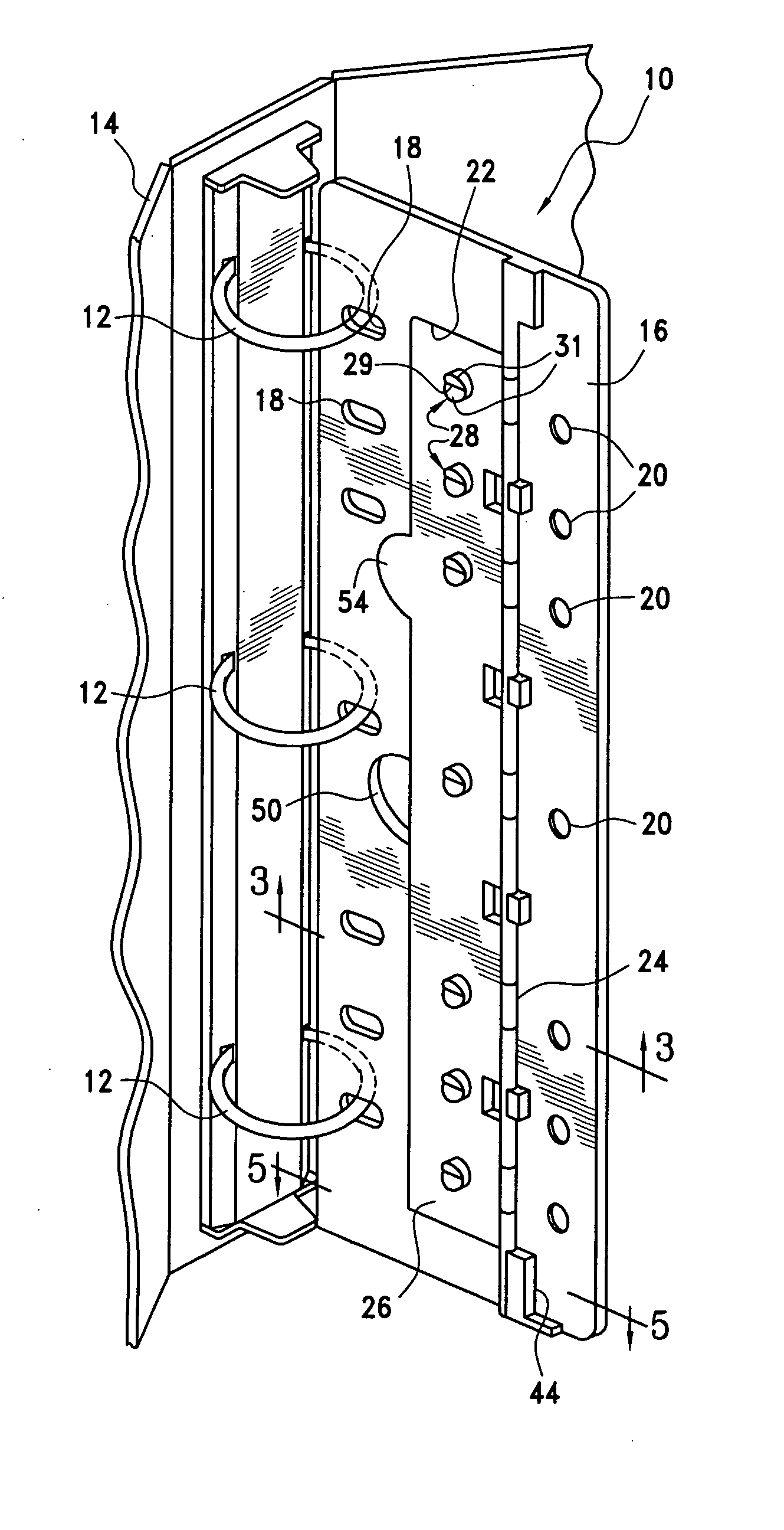
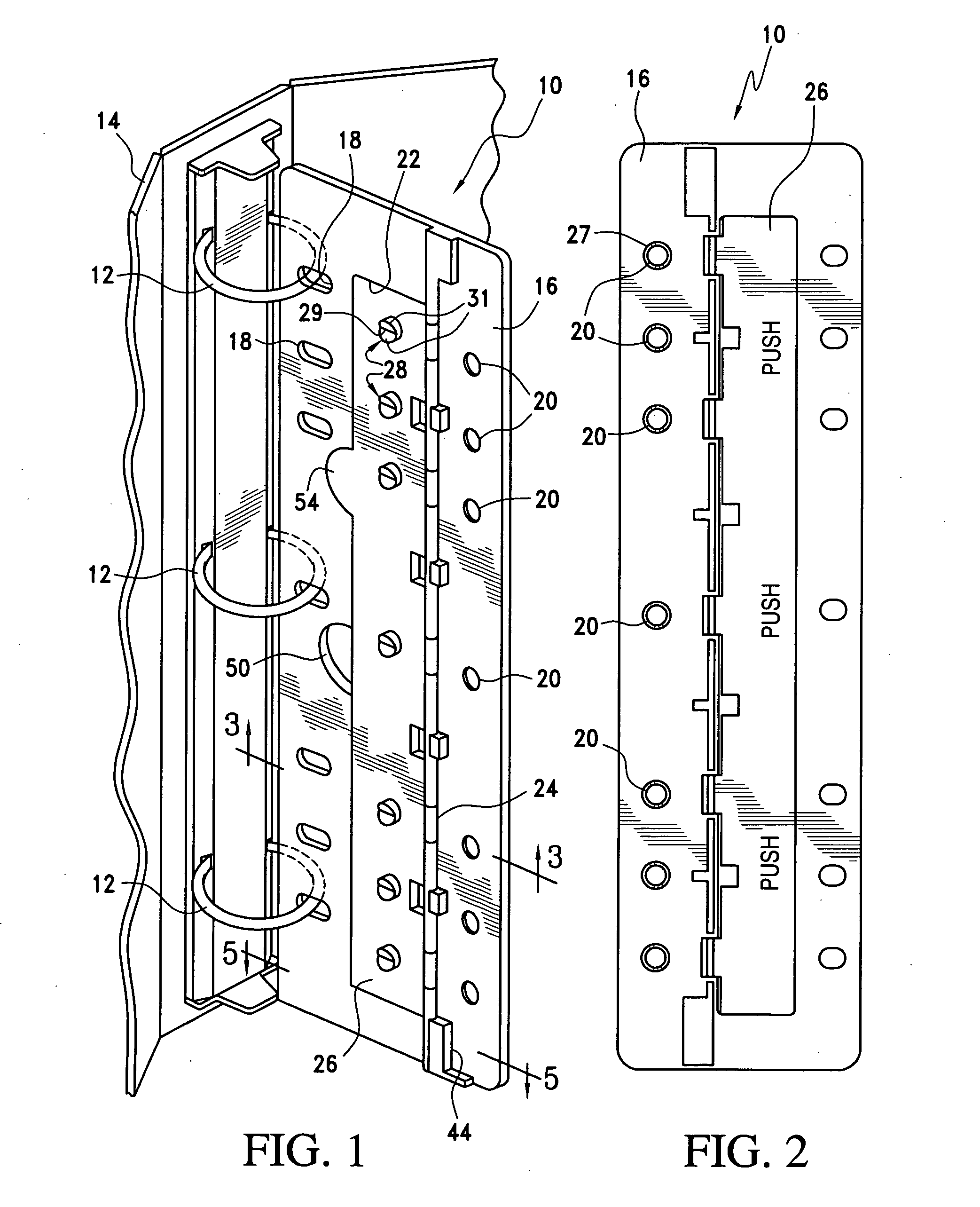
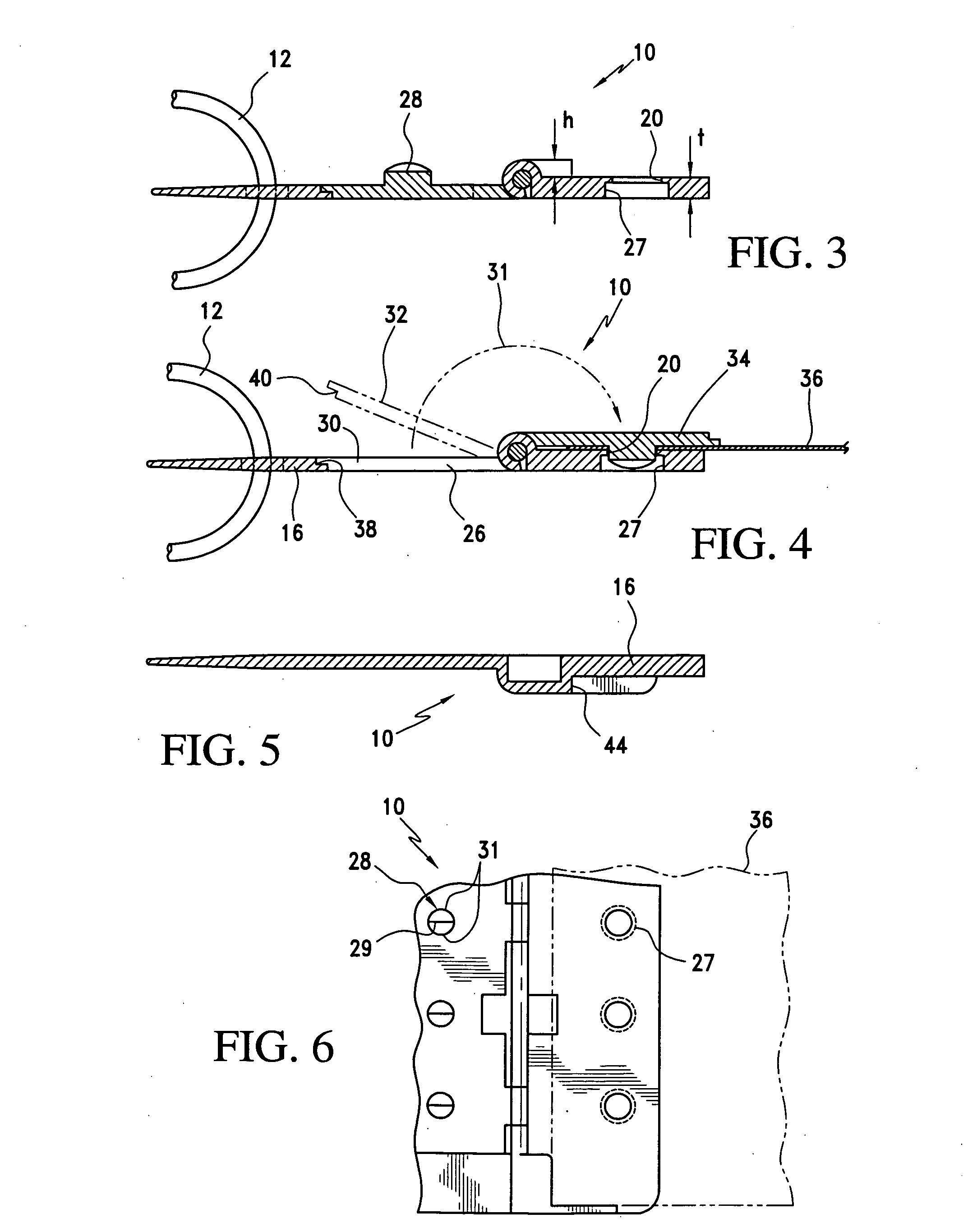
[0021]Referring to the drawings and the characters of reference marked thereon, FIG. 1 illustrates the notebook insert of the present invention, designated generally as 10 shown attached to the rings 12 of a conventional ringed binder, designated generally as 14. Notebook insert 10 includes a housing 16 which comprises a first rigid, substantially flat plate. Housing or first plate 16 has a first set of a plurality of spaced holes 18 formed therethrough along a first side thereof. This first set of holes 18 are spaced and sized for engagement with the rings 12 of the ringed notebook 14, as shown. The housing (or first plate) 16 further includes a second set of a plurality of spaced holes 20 formed on a second side of the housing 16. The housing 16 further includes an opening 22 in a central portion thereof. A plurality of spaced hinges 24 are located on a side edge of the side portion defined by the opening 22.

[0022]A second rigid plate 26 has a first side hingedly connected via the...


PUM


Abstract

A notebook insert that includes a housing including a first rigid substantially flat plate having a first set of a plurality of spaced holes formed therethrough a first side thereof. The first set of holes is adapted for engagement with the rings of a ringed notebook. The first rigid flat plate further has a second set of a plurality of spaced, stepped holes formed therethrough a second side thereof. The housing further includes an opening in a central portion thereof and a plurality of spaced hinges. The hinges are located on a side edge of the central portion defined by the opening. A second rigid plate has a first side hingedly connected via the spaced hinges to the first rigid plate. The second plate has a shape substantially matching the shape of the central opening so when the second rigid plate is in a stowed position it may be supported within the central opening. The second plate includes spaced projections formed on an upper surface thereof. The projections are so sized and spaced to align with the second set of spaced holes in the first plate when the second plate is rotated away from the stowed position so as to provide a holepunching capability when paper is inserted between an upper surface of the first plate and the second plate. The stepped holes have increased diameters at lower surfaces thereof that allow chads to be cleanly and easily be punched therethrough and released from the stepped holes when the second rigid plate is rotated away after punching paper. The stepped holes provide enhanced ease in disengaging the second rigid plate from the first rigid plate when rotating it back into position.

Description

BACKGROUND OF THE INVENTION[0001]1. Field of the Invention[0002]The present invention relates to inserts for notebooks and more particularly to a notebook insert which is securable to the rings of a notebook and has a holepunch mechanism which is capable of punching paper while remaining attached to the rings of the ringed binder.[0003]2. Description of the Related Art[0004]Users of notebooks, including businessmen and students, often desire to have various articles such as pencils and pens at their easy disposal when they use their notebook and to be secure from being lost when they carry their notebooks from one location to another.[0005]In partial solution to this problem, present applicant Mark A. Bedol, invented a “Notebook Organizer Including Slidable Element”, U.S. Pat. No. 5,050,736. The '736 patent discloses an organizer comprising a base with holes for engagement with the rings of a ringed notebook. The base includes a plurality of partitions which divide the base into a p...

Claims


Application Information

Patent Timeline
Patent Type & Authority Applications(United States)
IPC IPC(8): B42F13/00
CPCB42F13/404
Inventor BEDOL, MARK A.
Owner BEDOL MARK A
Why Eureka
Try Eureka