Rotor blade profile optimization

a technology of rotor blades and profiles, applied in the direction of marine propulsion, vessel construction, other chemical processes, etc., can solve the problems of reducing the operating performance of the engine, reducing the service life of the blades, and requiring balancing design constraints

Active Publication Date: 2008-05-01
GENERAL ELECTRIC CO
View PDF22 Cites 77 Cited by
  • Summary
  • Abstract
  • Description
  • Claims
  • Application Information

AI Technical Summary

Benefits of technology

[0007]In another aspect, a high-pressure turbine is provided. The high-pressure turbine includes at least one row of rotor blades. Each of the rotor blades includes a platform and an airfoil extending therefrom. At least one of the airfoils includes an airfoil shape having a nominal ...

Problems solved by technology

In addition, as existing turbine rotor blade airfoils reach the end of their useful life cycle, replacement of the airfoils with redesigned airfoils is often necessary to accommodate the higher temperatures and higher pressures.
As a result of their exposure to hot combustion gases, such blades may be subjected to high stress and high temperatures caused by thermal gradients and mechanical loadings in the blades.
Over time, because of continued exposure to the combustion gases, such blades may bow, creep, and/or crack thereby reducing the operating performance of the engine.
Often, the design constraints require balancing.
For example, longer airfoil chord lengths may negatively impact the life of rotor blades by moving natural frequencies of the blades into an operating range of the turbofan engine assembly at selected operating sp...

Method used


Image

  • Rotor blade profile optimization
  • Rotor blade profile optimization
  • Rotor blade profile optimization

Examples


Embodiment Construction

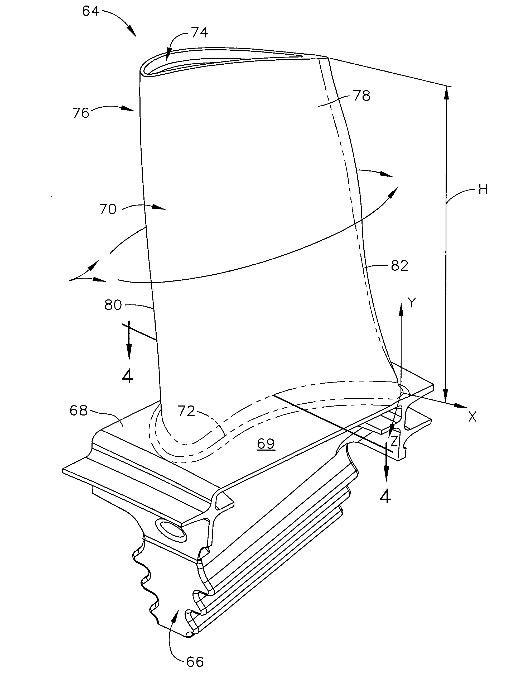
[0014]The exemplary rotor blade profiles described herein overcome the disadvantages of known rotor blade profiles by substantially tailoring the entire trailing edge profile.

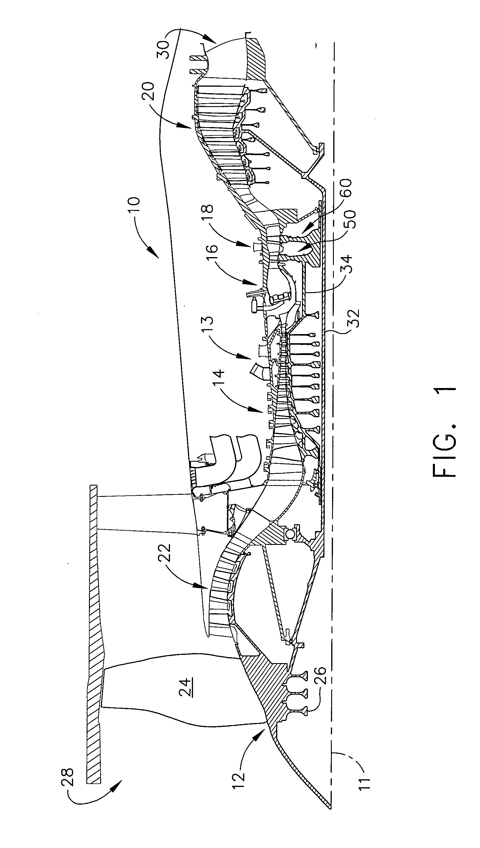
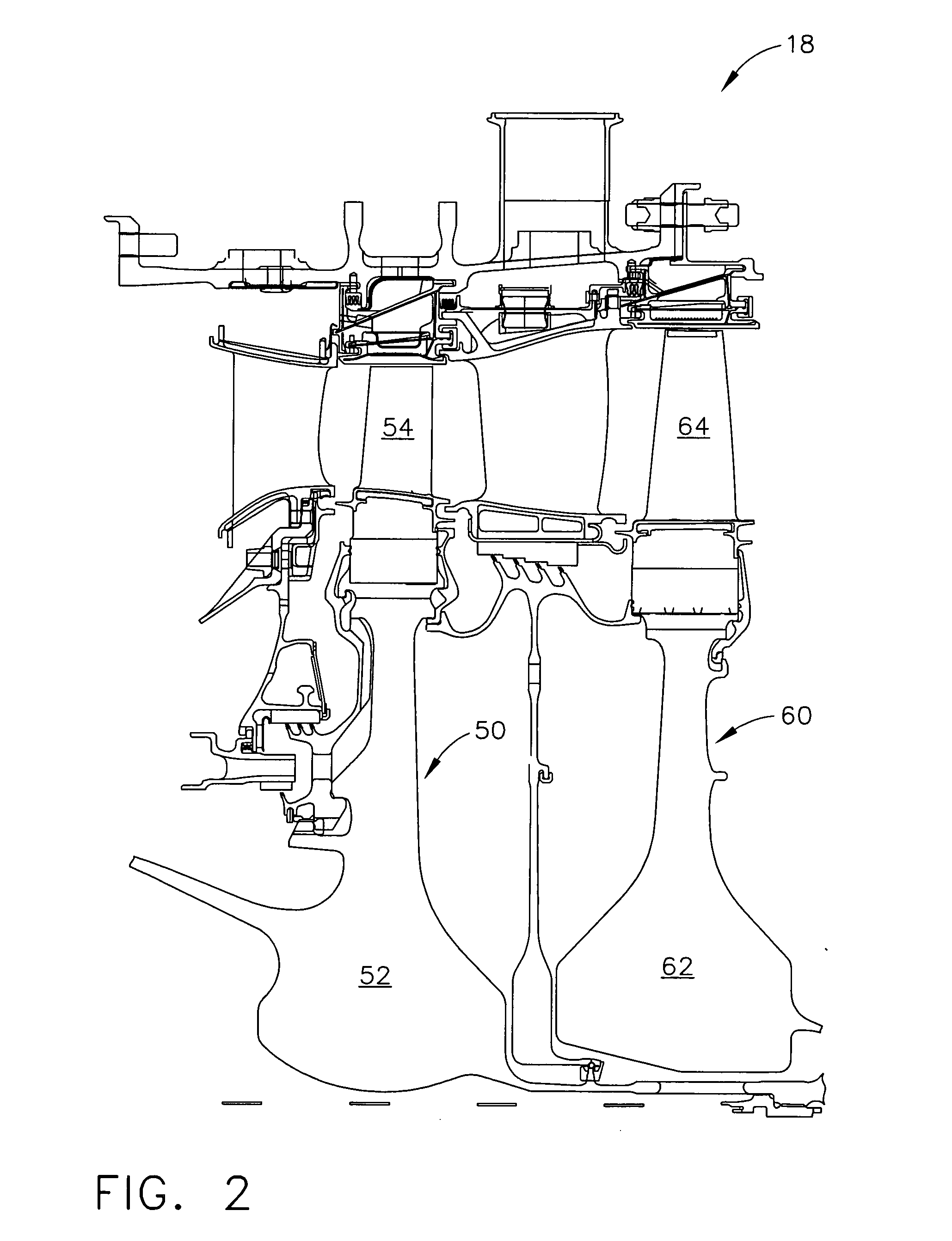
[0015]FIG. 1 is a cross-sectional view of a portion of an exemplary turbofan engine assembly 10 having a longitudinal axis 11. In the exemplary embodiment, turbofan engine assembly 10 includes a fan assembly 12, a core gas turbine engine 13 that is downstream from fan assembly 12, and a low-pressure turbine 20 that is downstream from core gas turbine engine 13. Core gas turbine engine 13 includes a high-pressure compressor 14, a combustor 16, and a high-pressure turbine 18. In the exemplary embodiment, turbofan engine assembly 10 also includes a multi-stage booster compressor 22. Fan assembly 12 includes an array of fan blades 24 that extends radially outward from a rotor disk 26. Turbofan engine assembly 10 has an intake side 28 and an exhaust side 30. Moreover, turbofan engine assembly 10 includes a first rot...


PUM


Abstract

An airfoil for a rotor blade including an uncoated profile substantially in accordance with Cartesian coordinate values of X, Y and Z to facilitate balancing performance and durability of the rotor blade and to facilitate improving an operating efficiency of a high-pressure turbine is provided. The profile is carried only to four decimal places, wherein Y represents a distance from a platform on which the airfoil is mounted, and X and Z are coordinates defining the profile at each distance Y from the platform.

Description

BACKGROUND OF THE INVENTION[0001]This application relates generally to gas turbine engine assemblies and more particularly, to turbine rotor blade airfoil profiles.[0002]In the design, fabrication, and use of turbofan engine assemblies, there has been an increasing tendency towards operating with higher temperatures and higher pressures to optimize turbine performance. In addition, as existing turbine rotor blade airfoils reach the end of their useful life cycle, replacement of the airfoils with redesigned airfoils is often necessary to accommodate the higher temperatures and higher pressures. Moreover, airfoil redesign is desirable without altering or changing other parts of the turbofan engine assemblies.[0003]At least some known rotor blade airfoils are exposed to hot combustion gases. For example, some known turbofan engine assemblies include a combustor that is upstream of a high-pressure turbine. Combustion gases discharged from the combustor flow past the rotor blades. As a r...

Claims


Application Information

Patent Timeline
IPC IPC(8): B64C27/46
CPCF05D2250/74F01D5/141Y10S416/02
Inventor MCRAE, RONALD EUGENEKEITH, BRIAN DAVIDOBERMEYER, ANDREW EDWARDLEEKE, LESLIE EUGENE
Owner GENERAL ELECTRIC CO
Why Eureka
Try Eureka