Broadcast method and system

a broadcast method and broadcast technology, applied in the field of broadcasting methods, can solve problems such as difficulties in ensuring proper equipment configuration

Active Publication Date: 2008-05-01
LEVEL 3 COMM LLC
View PDF20 Cites 28 Cited by
  • Summary
  • Abstract
  • Description
  • Claims
  • Application Information

AI Technical Summary

Benefits of technology

[0009]In accordance with alternate preferred embodiments a system for airing broadcast signals over a broadcast network preferably includes a production truck interface panel receiving a broadcast signal from a broadcast signal provider, a transmission relay circuit of a demarcation/equipment cabinet receiving the broadcast signal, and an operations control station communicating with the transmission relay circuit for displaying the type of broadcast signal determined by the broadcast signal sensing and discerning circuit. The transmission relay circuit preferably provides a broadcast signal sensing and discerning circuit, and a signal processing circuit. The broadcast signal detection circuit is preferably configured for determining a signal type of the broadcast signal, and the signal processing circuit is preferably configured for processing the determined signal type. The type of broadcast signal determined is preferably selected from a group consisting of (NTSC, DS-3, ASI, SDI, and HD-SDI video signals).
[0010]Preferably the broadcast signal airing system further includes television signal receiving and transmission equipment communicating with the transmission relay circuit for advancing the broadcast sig

Problems solved by technology

The multiplicity of signal types, combined with the use of a backbones of information networks for high speed, and world wide deployment of event broadcasts have created difficulties in assuring proper configuration of equipment is present and fully operative through out the

Method used


Image

  • Broadcast method and system
  • Broadcast method and system
  • Broadcast method and system

Examples


Embodiment Construction

[0022]Reference will now be made in detail to one or more examples of the invention depicted in the figures. Each example is provided by way of explanation of the invention, and not meant as a limitation of the invention. For example, features illustrated or described as part of one embodiment may be used with another embodiment to yield still a different embodiment. Other modifications and variations to the described embodiments are also contemplated within the scope and spirit of the invention.

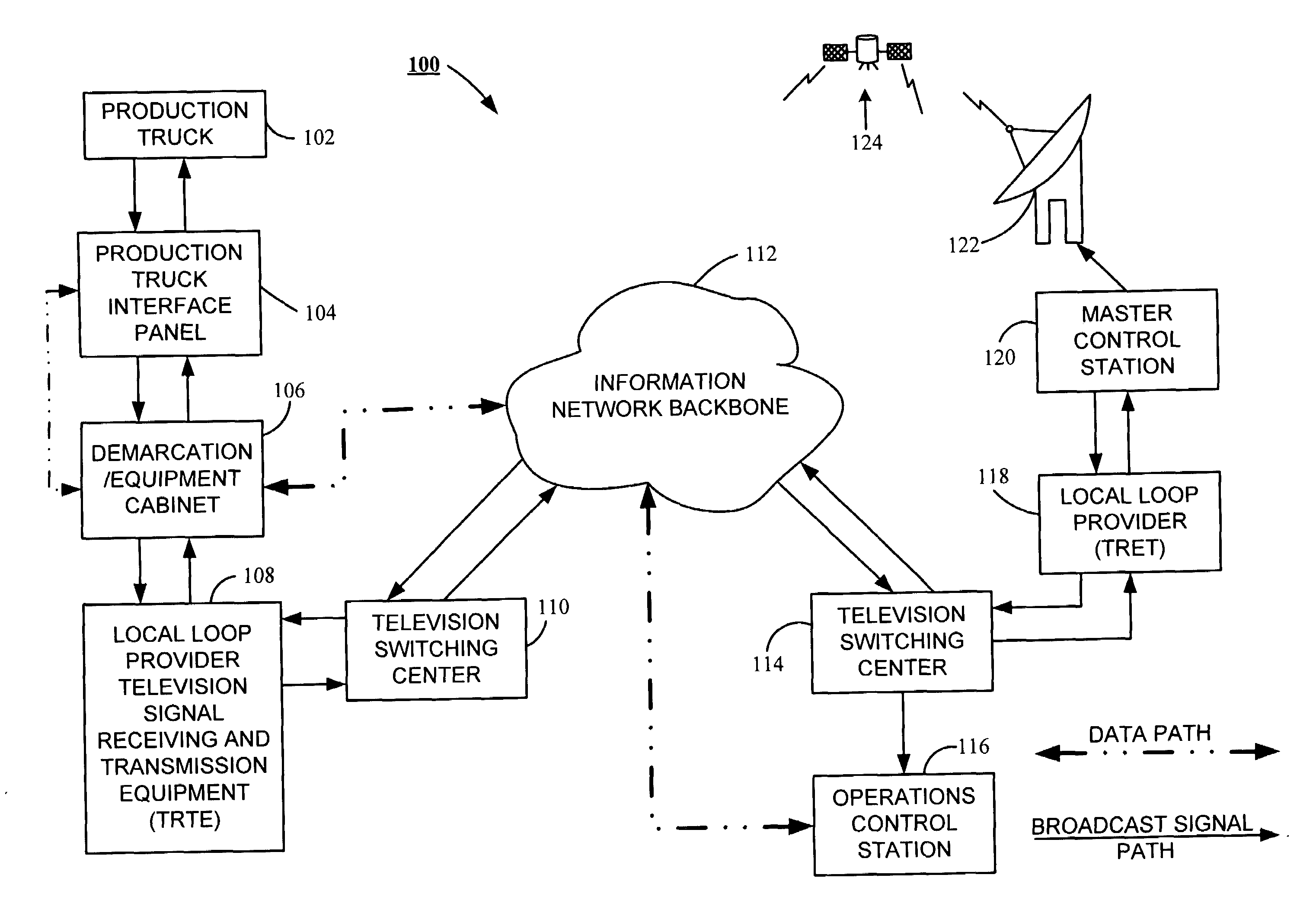
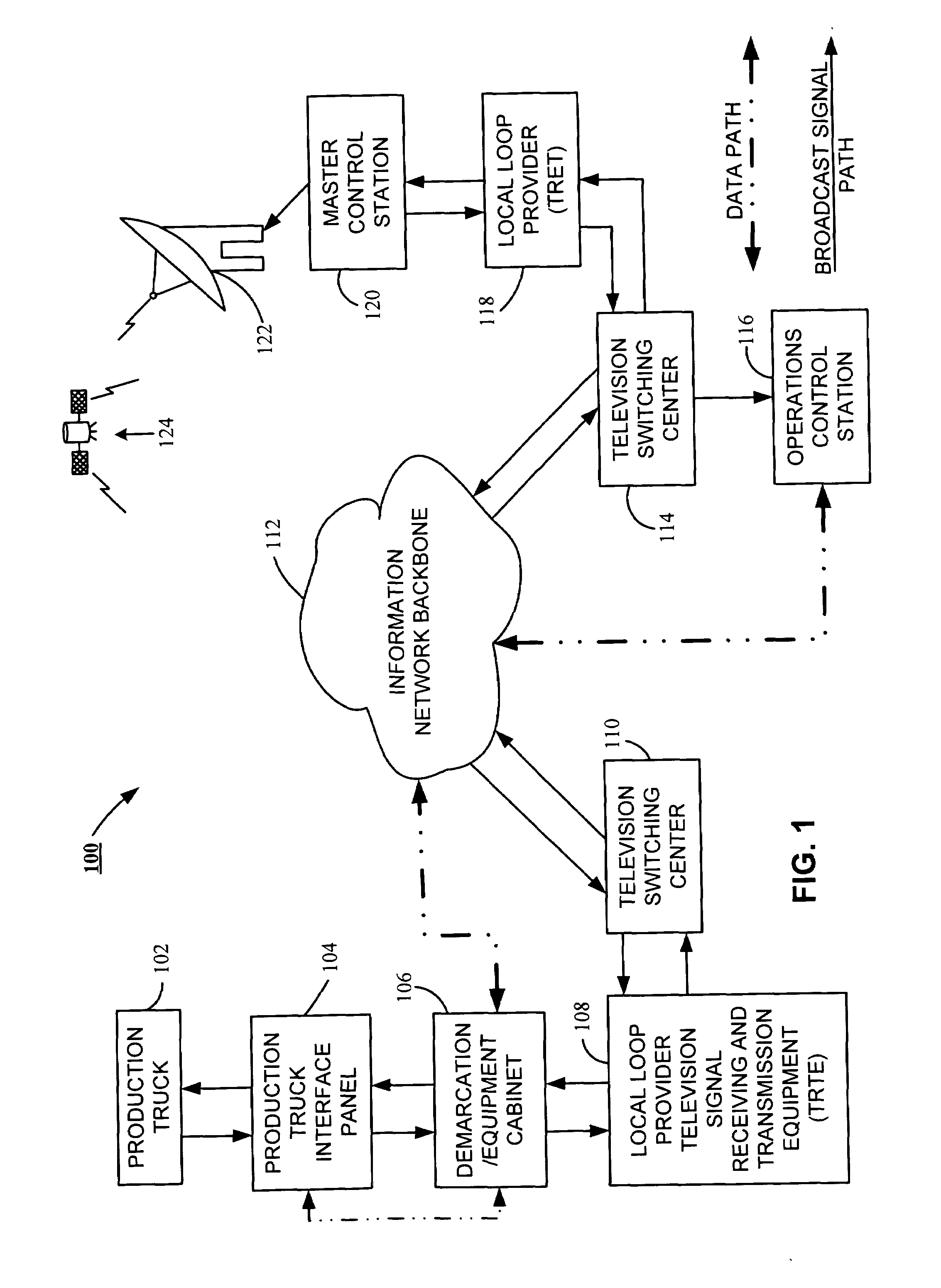
[0023]Referring to the drawings, FIG. 1 shows an inventive broadcast network 100 for airing a broadcast signal generated by a broadcast signal provider, such as ESPN, FOX, CBS, NBC, and ABC. The broadcast network 100 preferably includes a production truck 102, which receives multiple signals from television cameras recording events such as football games, baseball games, hockey games, and other events of interest. Personnel within the production truck 102 make decisions on a continuing basis...


PUM


Abstract

A method and system for airing broadcast signals is disclosed. Preferably, the system includes a production truck interface panel receiving a broadcast signal. A transmission relay circuit relays the signal from the interface panel to a broadcast network, and preferably including a broadcast signal detection circuit, and a signal processing circuit. The detection circuit determines a signal type of the broadcast signal, and the signal processing circuit processes the determined signal type. The system preferably further includes an operations control station displaying the determined type of broadcast signal. The method for airing broadcast signals over the broadcast network preferably includes the steps of providing the broadcast signal to the transmission relay circuit, detecting the broadcast signal type with the broadcast signal sensing and discerning circuit; and reconfiguring the signal processing circuit when the configuration of the signal processing circuit does not support transmission of the determined broadcast signal type.

Description

FIELD OF THE INVENTION[0001]The claimed invention relates generally to the field of signal processing and transmission and more particularly, but not by way of limitation, to a system and associated method for processing, distributing, and broadcasting television signals.BACKGROUND[0002]Systems and methods for televising events, such as live sporting events, are known and have been in place for at least a half century, and for nearly all of that time analog video signal generation and processing equipment was not only the preferred approach to television broadcasting, it was the only approach to television broadcasting.[0003]Within the North American broadcast market, NTSC analog video signals had been the standard for the broadcast industry since 1940 when the Federal Communications Commission adopted the standard, however more recently a number of alternate digital signaling technologies have come into use and have changed the dynamics of how events are broadcast. Those signaling ...

Claims


Application Information

Patent Timeline
IPC IPC(8): H04B3/36H04Q7/20H04B7/14H04H1/00
CPCH04H60/05H04H60/07H04N5/28H04N5/268H04N5/222H04H20/04H04H20/12H04L41/22H04N5/38
Inventor KEENER, DAVID J.JONES, JOHN S.WARD, PETER L.
Owner LEVEL 3 COMM LLC
Why Eureka
Try Eureka