Endoscopic device insertable into a body cavity and movable in a predetermined direction, and method of moving the endoscopic device in the body cavity

a technology of endoscopic examination and body cavity, which is applied in the field of endoscopic examination devices, can solve the problems of pain to patients, inability to use in practice, and difficult problems for medical personnel

Inactive Publication Date: 2008-05-01
MOTUS GI MEDICAL TECH LTD
View PDF11 Cites 9 Cited by
  • Summary
  • Abstract
  • Description
  • Claims
  • Application Information

AI Technical Summary

Benefits of technology

[0006] Accordingly, it is an object of the present invention to provide an endoscopic device insertable into a body cavity and movable in a predetermined direction, which avoids the disadvantages of the prior art.

Problems solved by technology

There are many devices of this type; however they are not used in practice.
Taking into consideration that the intestine has a complicated shape and length about 1.5 meter it is quite a difficult problem for the medical personnel.
During this process, the intestine is subjected to significant deformations which cause pain to a patient and sometimes perforations of an intestine wall.
This poses the major problem since the walls of the intestine are very slippery, thin and elastic in a transverse direction.
The attaching elements formed in this way are not efficient, since the openings in them are very small.
In addition they are arranged over the whole surface of the cylinders, so that generation of a vacuum is not guaranteed.
If level of vacuum is increased in order to improve efficiency, the walls of the intestine can be damaged.
Also, the negative factor from the point of view of safety of intestine walls is that during the movement the attaching elements formed in this way pass the same point twice, by the front attaching element and then by the rear attaching element.
Also, it is difficult to connect additional diagnostic or treatment elements to the device disclosed in this reference.
While this device can be considered an improvement, the disadvantage of this device is the particular trajectory of movement, in accordance with which the two attaching elements move one after the other over the same line.
When one of the attaching elements is detached from the wall of the intestine the intestine is immediately deformed back, which causes the corresponding problems.

Method used


Image

  • Endoscopic device insertable into a body cavity and movable in a predetermined direction, and method of moving the endoscopic device in the body cavity
  • Endoscopic device insertable into a body cavity and movable in a predetermined direction, and method of moving the endoscopic device in the body cavity
  • Endoscopic device insertable into a body cavity and movable in a predetermined direction, and method of moving the endoscopic device in the body cavity

Examples


Embodiment Construction

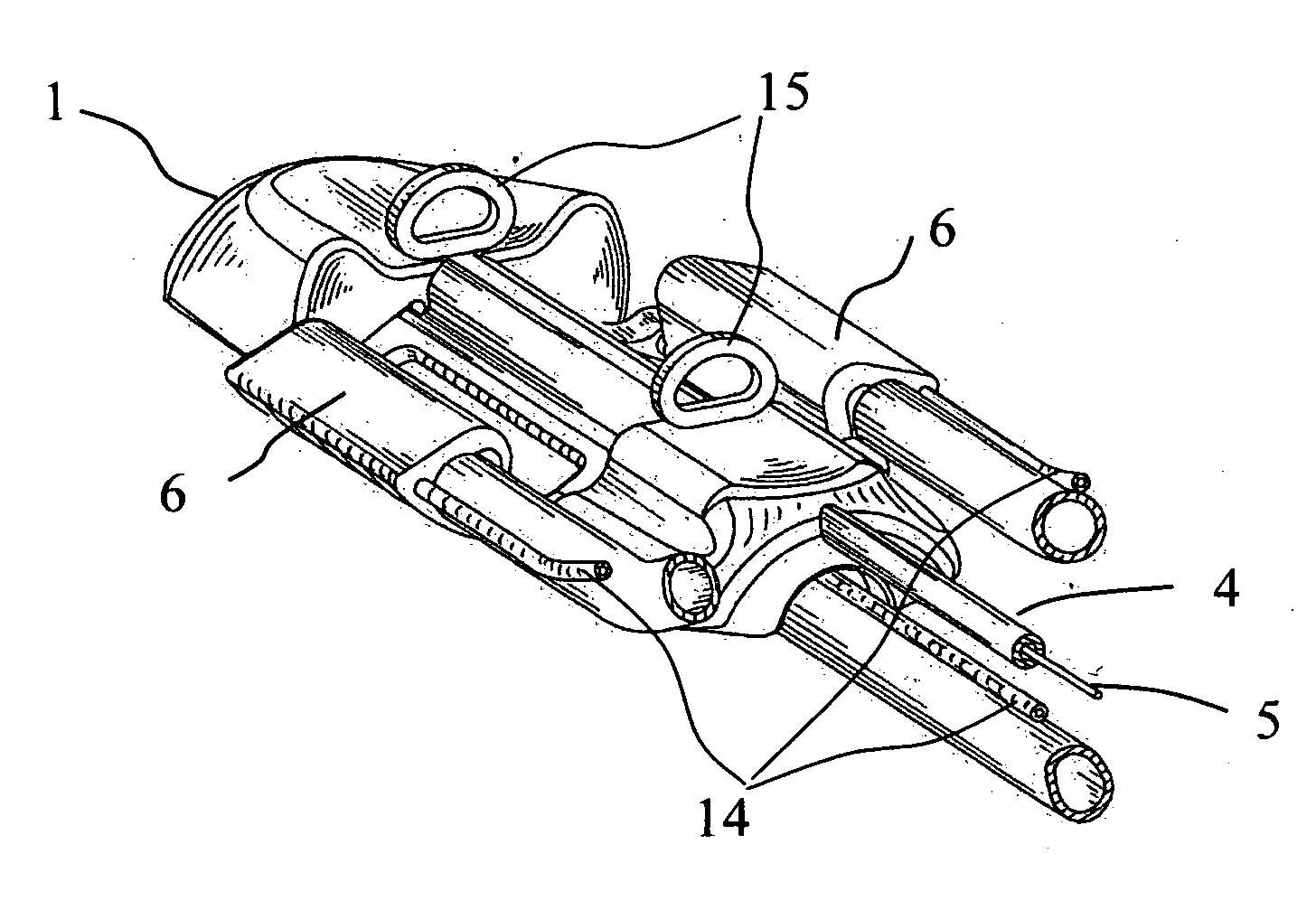
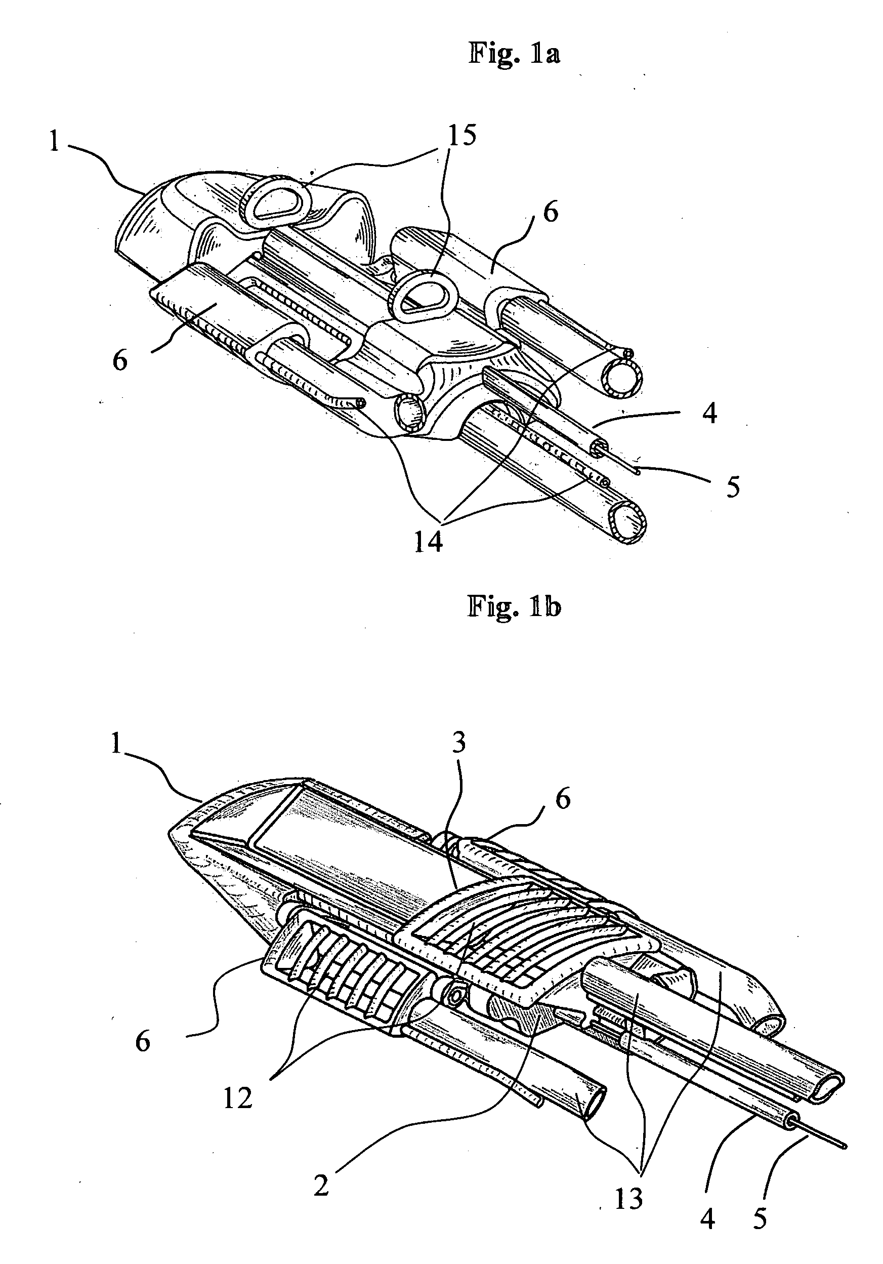
[0030] The endoscopic device in accordance with the present invention, which is insertable into a body cavity and movable in a predetermined direction has a housing which is identified with reference numeral 1. The housing is substantially elongated in a direction of a longitudinal axis and does not have any sharp edges to prevent damages to a wall of a body cavity, such as an intestine. The housing 1 in its interior has an omega-shaped slot 2, shown in FIGS. 1 and 3 that extends in a longitudinal direction.

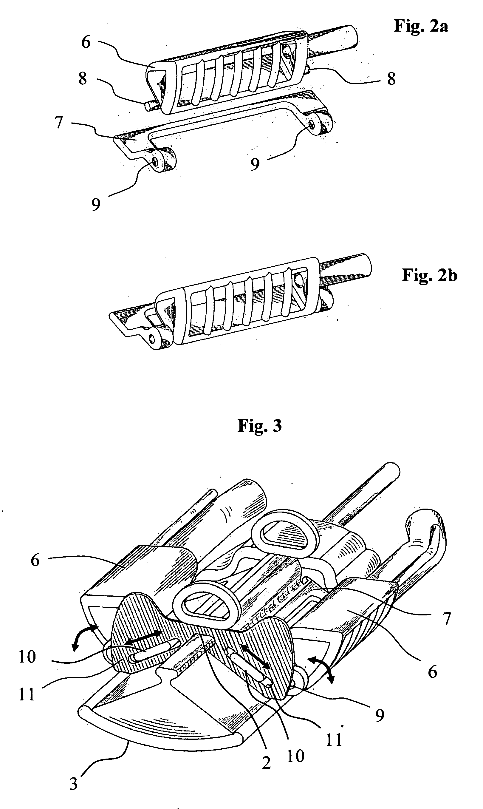
[0031] The device in accordance with the present invention has a movable attaching element which is identified with reference numeral 3. The movable attaching element 3 is movable relative to the housing 1 and guided by the slot 2. In particular, a projection of the movable attaching element 3 engages in the slot 2 provided in the housing.

[0032] A force required for movement of the movable attaching element 3 relative to the housing 1 and relative to a wall of the body cavity, ...


PUM


Abstract

In an endoscopic device insertable into a body cavity attachable elements are moved over one another to move forwardly of each other and to leave each other behind, and to move along different paths so as not to be attached to the same areas of a wall of the body cavity.

Description

BACKGROUND OF THE INVENTION [0001] The present invention relates to devices for endoscopic examination which are movable in a body cavity in a predetermined direction without pushing from outside, for example in intestine and can carry equipment that are necessary for diagnostics and treatment of the intestine. It also relates to a method of moving such devices in a body cavity. [0002] There are many devices of this type; however they are not used in practice. Medical personnel move medical instruments and diagnostic equipment into intestine manually. Taking into consideration that the intestine has a complicated shape and length about 1.5 meter it is quite a difficult problem for the medical personnel. During this process, the intestine is subjected to significant deformations which cause pain to a patient and sometimes perforations of an intestine wall. The above mentioned deformations are caused, because along the whole length of the intestine the direction of a force which moves...

Claims


Application Information

Patent Timeline
Patent Type & Authority Applications(United States)
IPC IPC(8): A61B1/00
CPCA61B1/00094A61B1/00156A61B1/00147A61B1/126A61B1/0014A61B1/005
Inventor SHTUL, BORIS
Owner MOTUS GI MEDICAL TECH LTD
Why Eureka
Try Eureka