
Cooking device

a technology of cooking device and cooking chamber, which is applied in the direction of electric/magnetic/electromagnetic heating, domestic stoves or ranges, lighting and heating apparatus, etc., can solve the problems of limiting the implementation of optimal cooking mode and uniform heating

Active Publication Date: 2008-05-08
LG ELECTRONICS INC
View PDF7 Cites 62 Cited by
  • Summary
  • Abstract
  • Description
  • Claims
  • Application Information

AI Technical Summary

Benefits of technology

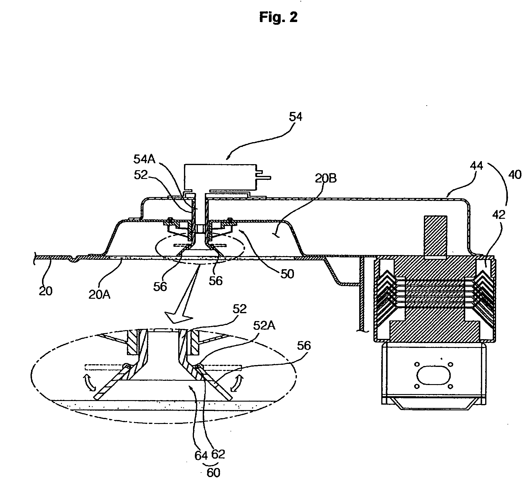
The present invention provides a cooking device with a stirring vane that can rotate around a virtual axis vertical to a stirring shaft, which causes a variation in the radiation condition of microwaves depending on the load being cooked. The hinge unit allows the stirring vane to rotate about an axis perpendicular to the rotational axis of the stirring shaft. The stirring vane is inserted into the stirring shaft and is supported against gravity by a hinge stopper. The hinge unit includes a hinge resilient member and a hinge loop latched to the stirring shaft and the stirring vane. The stirring vane is rotated by centrifugal force and is protected from food and drink or heat within the cooking chamber by a barrier made of mica. The technical effect of the invention is to provide an optimal cooking mode for various conditions by varying the radiation condition of microwaves according to the load being cooked.

Problems solved by technology

However, considering that the condition of the radiation of the microwaves is an important factor not only in the intensity of the microwaves, but also in the phase thereof, there is a limit to the implementation of an optimal cooking mode as well as uniform heating according to various conditions of a load depending on the type of a load, the location of a load, and the like, because the stirrer rotates in two dimensions or makes tracking movements in two dimensions.

Method used


Image

  • Cooking device
  • Cooking device
  • Cooking device

Examples


Embodiment Construction

[0028] The present invention will now be described in detail in connection with specific embodiments with reference to the accompanying drawings. The particulars shown herein are by way of example and for purposes of illustrative discussion of the embodiments of the present invention only and are presented in the cause of providing what is believed to be the most useful and readily understood description of the principles and conceptual aspects of the present invention. In this regard, no attempt is made to show structural details of the present invention in more detail than is necessary for the fundamental understanding of the present invention, the description is taken with the drawings making apparent to those skilled in the art how the forms of the present invention may be embodied in practice.

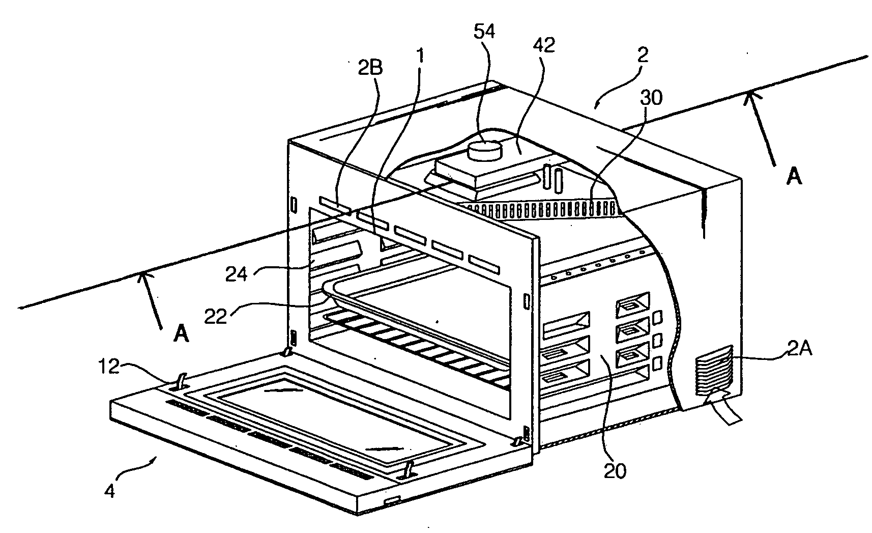
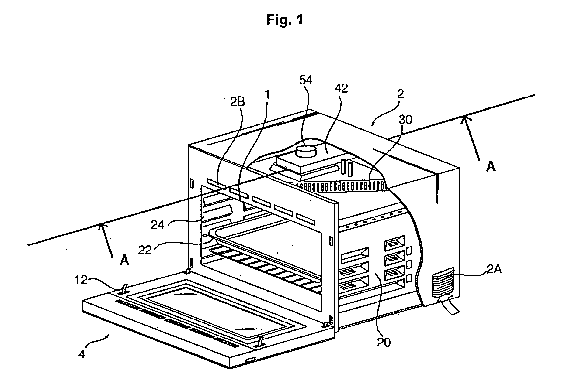
[0029]FIG. 1 is a perspective view illustrating a partially cut away exterior of a cooking device in accordance with a first embodiment of the present invention. FIG. 2 is a cross-section...


PUM


Abstract

A cooking device that cooks food and drink by using heat generation of a heater, or a heat source such as microwaves. A cooking device is provided in which the radiation of microwaves can be varied depending on load, such as cooking objects, when microwaves are used as a heat source. The cooking device includes a stirring shaft provided to rotate within a cooking chamber, a stirring shaft power source to rotate the stirring shaft, and a stirring vane coupled to the stirring shaft through a hinge unit and configured to rotate by a centrifugal force according to a rotation speed of the stirring shaft. The radiation of microwaves can be varied depending on a load such as a cooking object, and a cooking device having an optimized performance can be provided.

Description

CROSS REFERENCE TO RELATED APPLICATIONS [0001] The present disclosure relates to subject matter contained in priority Korean Patent Application No. 10-2006-0104882, filed on Oct. 27, 2006, the entire contents of which are hereby expressly incorporated by reference. BACKGROUND OF THE INVENTION [0002] 1. Field of the Invention [0003] The present invention relates to a cooking device for cooking food and drink by using heat generation of a heater, a heat source such as microwaves, or the like. More particularly, the present invention relates to a cooking device in which the radiation of microwaves can be varied depending on load, such as cooking objects, when microwaves are used as a heat source. [0004] 2. Discussion of Related Art [0005] In general, a cooking device is used to cook food and drink, cooking objects, which are contained in a cooking chamber, by using heat generation of a heater or a heat source such as microwaves. [0006] This cooking device generally includes a stirrer f...

Claims


Application Information

Patent Timeline
Patent Type & Authority Applications(United States)
IPC IPC(8): H05B6/72
CPCH05B6/745H05B6/74F24C7/067H05B6/6402
Inventor CHOI, HEUNG SHIKKIM, HYUN JUNG
Owner LG ELECTRONICS INC
Learn More