
Eureka
For R&D, Eureka makes reading and utilizing patents & technical documents easy.
Eureka AIR
Designed for self-driven R&D workflows. Generate viable solutions, solve complex R&D challenges, empower your innovation with AI.

Eureka Materials
Designed for material experts only. Revolutionize your material R&D, from search, analyze, to developing new materials.

TechResearch
Generate reliable direction feasibility study reports for your R&D in just a few steps.

TechSeek
Discover and master advanced knowledge NOW. Basics, ideas, possibilities, all at once.

TechMind
As an expert in R&D Theories, TechMind can generates customized viable solutions instantly.

TechRisk
Analyze your overall solution with one click, know your potential R&D risks in advance.

TechMonitor
Get weekly tech updates, stay abreast of the latest tech innovations and key insights.
Connecting assembly
- Summary
- Abstract
- Description
- Claims
- Application Information
AI Technical Summary
Benefits of technology
Problems solved by technology
Method used
Image

Examples
first embodiment
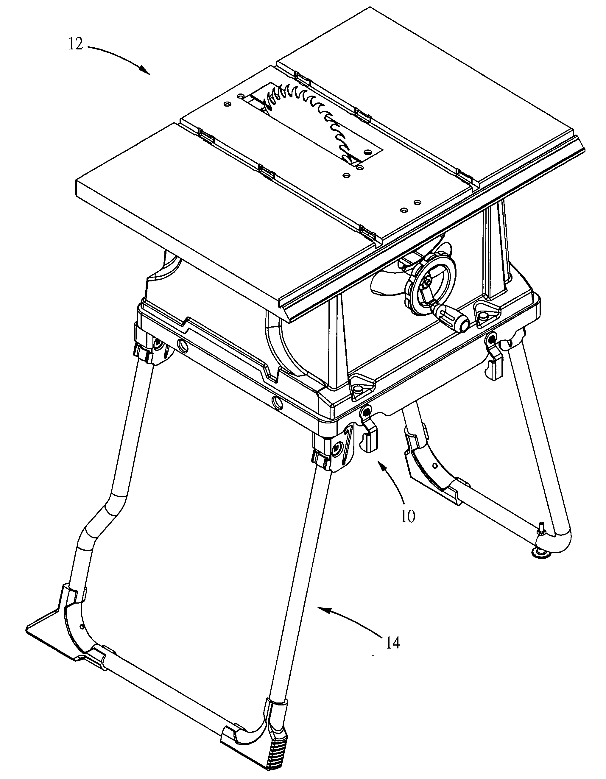
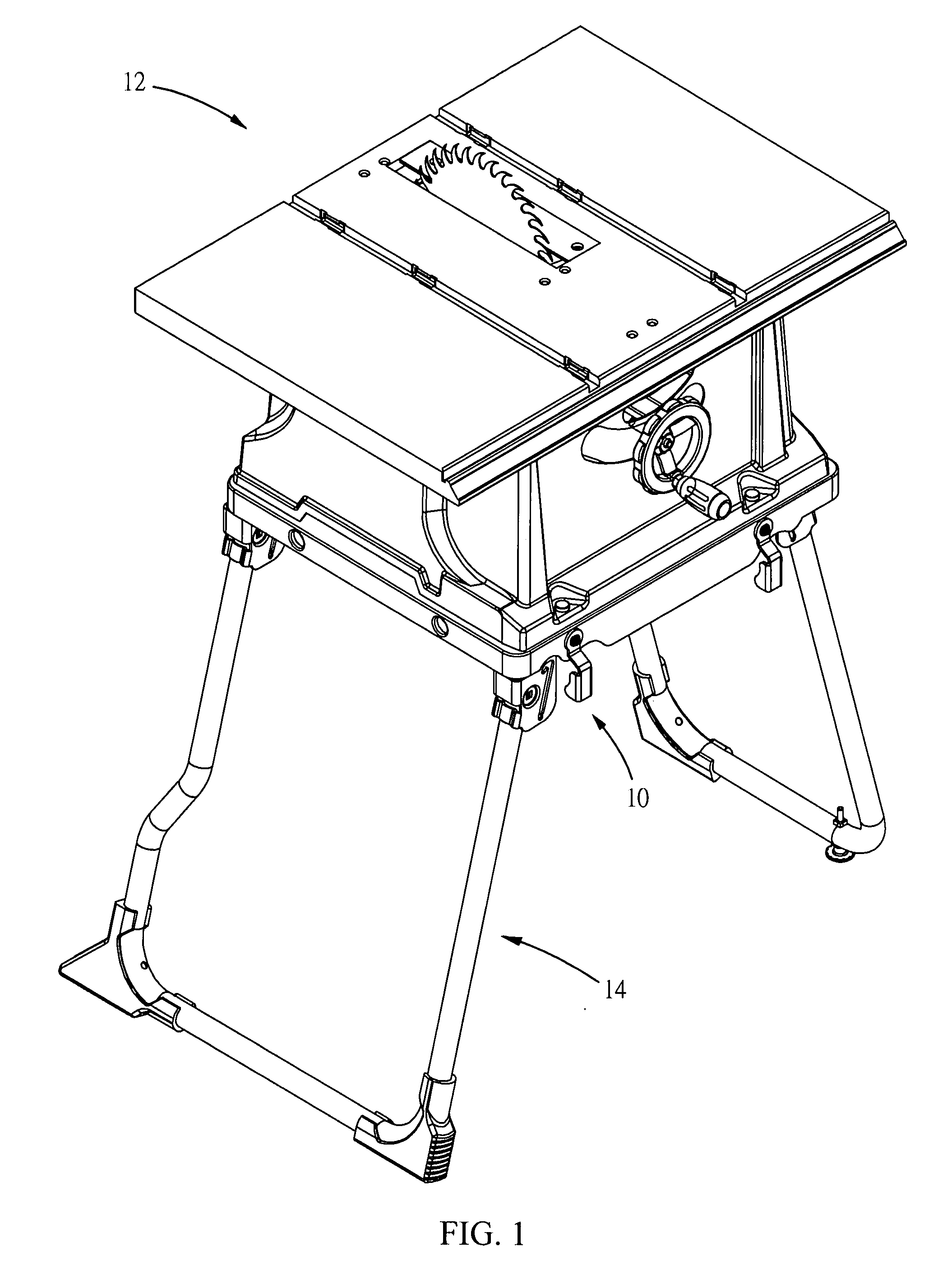
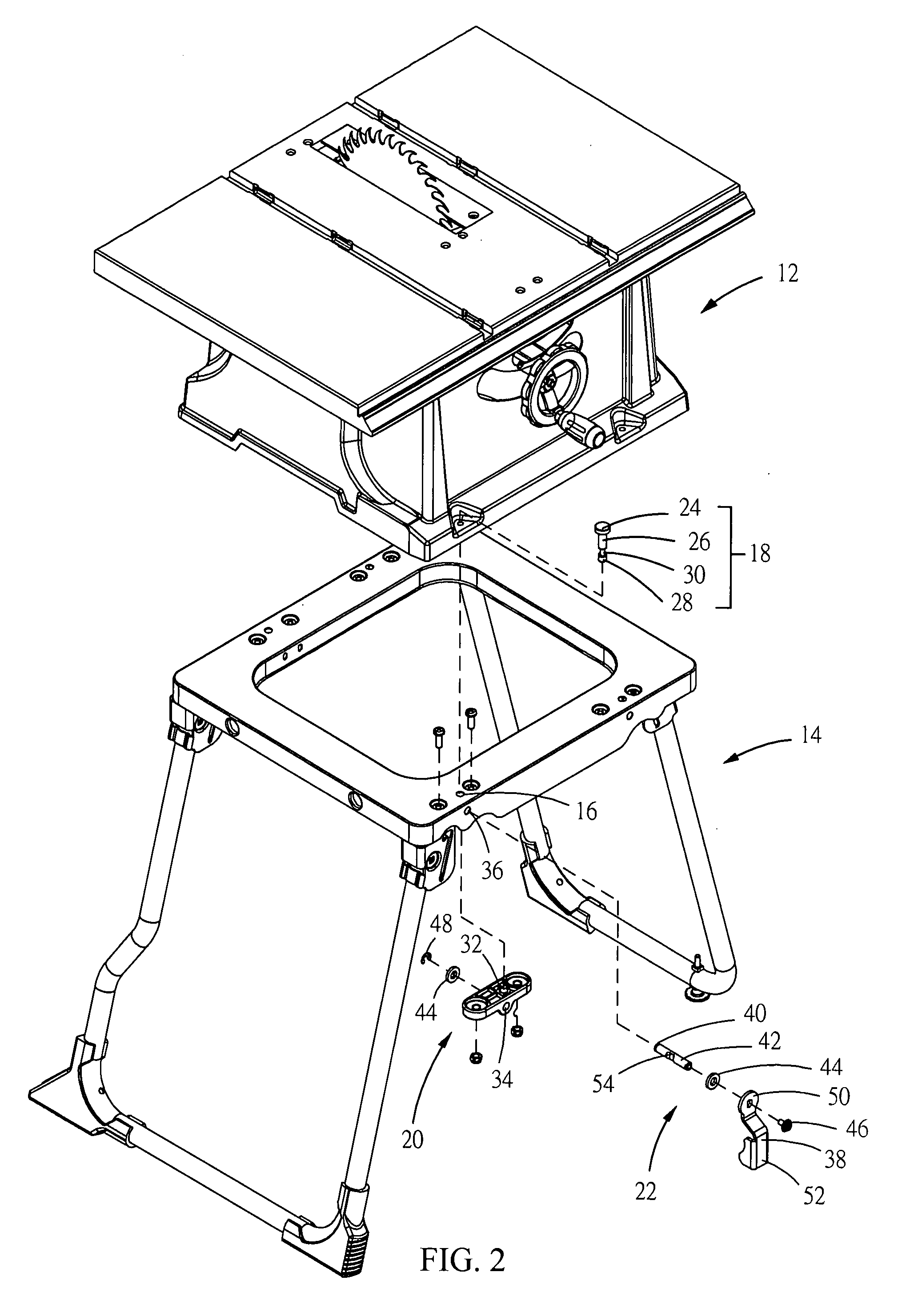
[0018]Referring to FIGS. 1 and 2, a connecting assembly 10 provided by a first embodiment is used to connect a power tool and a stand 14. The power tool is a commonly used woodworking machine, such as miter saw, table saw, scroll saw, band saw and sander, etc. A table saw 12 is taken as an example in the present embodiments. When performing a cutting operation, a user generally places the table saw 12 upon the stand 14 to have a predetermined height above the ground, such that the user can operate the table saw 12 conveniently. The top of the stand 14 is bored through with at least one hole 16. When a plug 18 is inserted into the bottom of the table saw 12, through the hole 16, and into a base 20 that is fixed on the stand 14 and is located underneath the hole 16 correspondingly, then the plug 18 can be locked by a lock assembly 22. Thus, the connecting assembly 10 is capable of mounting the table saw 12 securely onto the stand 14.
[0019]Referring to FIG. 2, the connecting assembly 1...
second embodiment
[0024]FIGS. 5 and 6 illustrate the locked and unlocked status of a connecting assembly of a second embodiment in accordance with the present disclosure. Referring to FIGS. 5 and 6, the connecting assembly comprises a plug 18, a base 20 and a lock assembly 22.
[0025]The plug 18 is the same as the described in the first embodiment.
[0026]The base 20 is fixed on the stand 14, and is correspondingly located underneath the hole 16 and includes a lead hole 32 and a cavity 56. The lead hole 32 corresponds to the hole 16. The cavity 56 and the lead hole 32 intercommunicate and are substantially perpendicular to each other.
[0027]The lock assembly 22 includes a rotatable cam 58, and a stop device 60 disposed between the cam 58 and the base 20. The cam 58 has a protruding portion 62. The distance from the protruding portion 62 to an axis 64 of the cam 58 is larger than the nearest distance from the periphery of the lead hole 32 to the axis of the cam 58. The stop device 60 includes a spring 66 a...
third embodiment
[0029]FIGS. 7 and 8 illustrate the locked and unlocked status of a connecting assembly of a third embodiment in accordance with the present disclosure. Referring to FIGS. 7 and 8, the connecting assembly comprises a plug 18, a base 20 and a lock assembly 22.
[0030]The plug 18 is the same as the described in the first embodiment.
[0031]The base 20 is fixed on the stand 14, and is correspondingly located underneath the hole 16 and includes a lead hole 32 and a cavity 74. The lead hole 32 corresponds to the hole 16. The cavity 74 and the lead hole 32 intercommunicate and are substantially perpendicular to each other.
[0032]The lock assembly 22 includes a sliding plate 76 that is slidable leftward and rightward in the cavity 74, and a spring 78 installed in the cavity 74. One end of the spring 78 contacts one end of the sliding plate 76 and the other end contacts one end of the cavity 74. A notch 80 is formed in the other end of the sliding plate 76 that is opposite to the end contacting t...
PUM
| Property | Measurement | Unit |
|---|---|---|
| Height | aaaaa | aaaaa |
Abstract
Description
Claims
Application Information
 - R&D Engineer
- R&D Manager
- IP Professional
- Industry Leading Data Capabilities
- Powerful AI technology
- Patent DNA Extraction
Browse by: Latest US Patents, China's latest patents, Technical Efficacy Thesaurus, Application Domain, Technology Topic, Popular Technical Reports.
© 2024 PatSnap. All rights reserved.Legal|Privacy policy|Modern Slavery Act Transparency Statement|Sitemap|About US| Contact US: help@patsnap.com