
On-vehicle radar device and on-vehicle radar device control system

Inactive Publication Date: 2008-05-08
FUJITSU GENERAL LTD +1
View PDF17 Cites 30 Cited by
  • Summary
  • Abstract
  • Description
  • Claims
  • Application Information

AI Technical Summary

Benefits of technology

[0010]To deal with this, an object of the present invention is to provide an on-vehicle radar device and the like which controls monitoring signals so that, within a dedicated band that can be set for a radar application, interference with other radar devices can be avoided with certainty.
[0012]By means of the above-mentioned first aspect, because, based on the relative priority order relative to another device, each device shifts the frequency band of its transmitted signal, overlap of the frequency band after shifting with other devices can be prevented and interference can thus be avoided.
[0014]By means of the above-mentioned second aspect, interference between the monitoring signal transmitted from the radar device mounted on a vehicle running ahead for monitoring the aft direction and the monitoring signal transmitted from the radar device of the device itself for monitoring the forward direction can be avoided.
[0016]By means of the radar device of the above-mentioned third aspect, interference with other devices can be more surely avoided by following an instruction from the control center, which has grasped the position of other nearby devices, and shifting the frequency band or transmission period.
[0017]By means of the radar device of the present invention, it is possible with certainty to avoid interference with other radar devices in the range of the available frequency band and to do so efficiently.

Problems solved by technology

As these radar devices become more widely adopted, there is a growing danger that as vehicles each of which has an on-vehicle radar device approach one another, interference between their radar devices will occur.
However, with the conventional technique there is the following kind of problem.
That is, even if in order to avoid interference among plurality of radar devices of the same model, the frequency band and / or the modulation cycle of the frequency are changed, if the operation of each is not done in an organized manner, eventually interference will reoccur.
In other words, if after changing, the frequency bands of the transmitted signals and / or the modulation cycles are not different one to the other, it is not possible to avoid interference with certainty.
Also, although it is true that interference could certainly be avoided if each radar device were allocated its own frequency band, it is not realistic to allocate in the commercial-use frequency band of 76.0 GHz to 77.0 GHz a different band to all the countless radar devices that exist.

Method used


Image

  • On-vehicle radar device and on-vehicle radar device control system
  • On-vehicle radar device and on-vehicle radar device control system
  • On-vehicle radar device and on-vehicle radar device control system

Examples


Embodiment Construction

[0028]Below, embodiments of the present invention will be described, according to the figures. However, the technical scope of the present invention is not limited by these embodiments, but extends to the items written in the patent claims and to equivalents thereto.

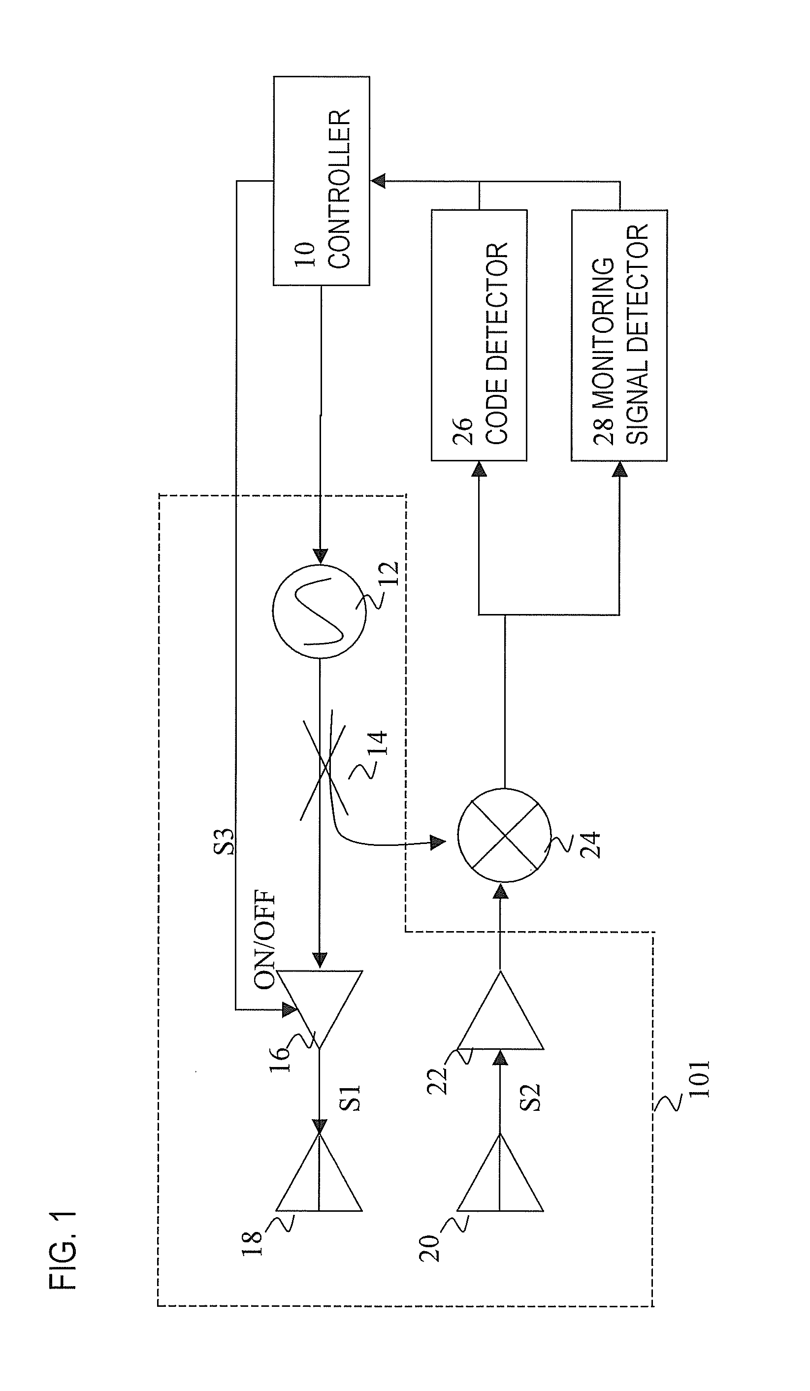
[0029]FIG. 1 is a configuration drawing of the on-vehicle radar device of the present embodiment. This on-vehicle radar device is an FM-CW radar device that performs frequency modulation of the transmitted signal, and is configured of a controller 10, an oscillator 12, a directionality coupler 14, a transmission amplifier 16, a transmission antenna 18, a reception antenna 20, a reception amplifier 22, a mixer 24, code detector 26, and a monitoring signal detector 28.

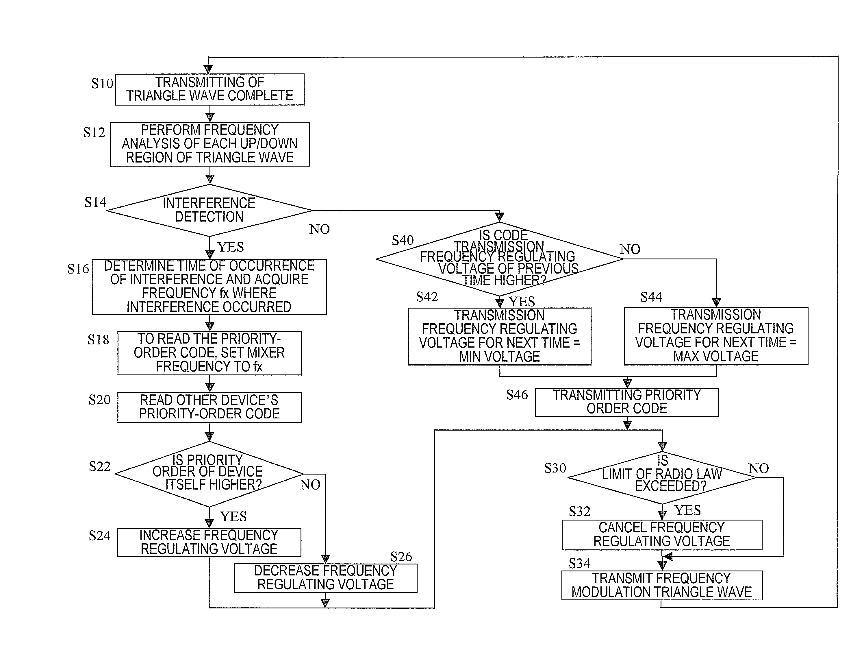
[0030]The on-vehicle radar device configured as indicated above, following a pre-determine rule, repeats alternately the operation of transmitting / receiving a monitoring signal frequency modulated by a constant frequency band width and the operation of transm...


PUM


Abstract

Provide an on-vehicle radar device that performs transmission control of a monitoring signal, following fixed rules, so that interference with other radar devices can be avoided with certainty. An on-vehicle radar device comprises a transceiver which transmits / receives a monitoring signal at a specified frequency band and transmits a priority order signal at a frequency within the above-mentioned frequency band, and a controller which switches the signals transmitted by the transceiver. The transceiver receives a priority order signal of another radar device, and when interference with the signal of the other radar device is detected, the controller, based on the priority order of that other device and on the priority order of the device itself, shifts, by a specified frequency amount, the frequency band of the monitoring signal transmitted by the transceiver.

Description

CROSS-REFERENCE TO RELATED APPLICATIONS[0001]This application is based upon and claims the benefit of priority from the prior Japanese Patent Application No. 2006-092964, filed on Mar. 30, 2006, the entire contents of which are incorporated herein by reference.BACKGROUND OF THE INVENTION[0002]1. Field of the Invention[0003]The present invention relates to an on-vehicle radar device and on-vehicle radar control system, and in particular to an on-vehicle radar device and on-vehicle radar control system which avoid interference between radar devices by shifting the frequency band or transmission period of the monitoring signal.[0004]2. Description of the Related Art[0005]As vehicle preventative safety systems, a variety of on-vehicle radar devices have been proposed that detect the distance to a vehicle running ahead and the relative speed. As these radar devices become more widely adopted, there is a growing danger that as vehicles each of which has an on-vehicle radar device approach...

Claims


Application Information

Patent Timeline
IPC IPC(8): G01S13/00G01S13/931
CPCG01S7/023G01S7/36G01S2013/936G01S13/931G01S13/34G01S13/345G01S2013/9316G01S7/0232G01S7/0235
Inventor HONDA, KANAKOISAJI, OSAMUSHIRAKAWA, KAZUOOHKUBO, NAOFUMISEKI, TETSUO
Owner FUJITSU GENERAL LTD
Features
  • Generate Ideas
  • Intellectual Property
  • Life Sciences
  • Materials
  • Tech Scout
  • Unparalleled Data Quality
  • Higher Quality Content
  • 60% Fewer Hallucinations
Learn More