Eureka AIR delivers breakthrough ideas for toughest innovation challenges, trusted by R&D personnel around the world.

Relief jet aperture swim fins with living-hinge blade

Inactive Publication Date: 2008-05-08
MELIUS JOHN DAVID
View PDF2 Cites 11 Cited by
  • Summary
  • Abstract
  • Description
  • Claims
  • Application Information

AI Technical Summary

Benefits of technology

[0016]The present invention also relates to a swim fin for use by a swimmer. The fin comprises a foot pocket adapted to receive a foot of the swimmer, a blade extending from the foot pocket, and a composite hydrodynamic flex control framework configured to allow the blade to bend closer to the heel than the toes of the swimmer within a narrow range of angles of attack requiring less effort under a wide range of loads. The wide range of loads comprises a light kick, a medium kick and a hard kick. The composite hydrodynamic flex control framework comprises a jet relief aperture as an aperture that along with a jet relief bevel separates the toe section of the foot pocket from the blade creating living hinges on the left and right side of the blade that controls the angle of attack of the blade with managed control of energy storage and the return of said stored energy to the blade.
[0018]The present invention further relates to a method of providing thrust from a kick by a swimmer. The method comprises providing a swim fin comprising a foot pocket, a blade, and one or more apertures that generally surround the toe section of the foot pocket, and one living hinge on the left side and one living hinge on the right side of the blade intersecting the foot pocket. The method also comprises bending the blade relative to the foot pocket about an axis and controlling the bending of the blade by providing increased resistance by the living hinges as the kicking power increases while the swimmer keeps the swimmer's feet in line with the swimmer's body and thus within the slip stream of the swimmer's body thus reducing drag. This kick is unusually small compared to traditional kicks with the swimmer needing only to move the swimmer's knees and feet as much as is needed for walking. In effect, the swimmer has a kick that is “walking-in-place” and one that reduces drag dramatically that is located closer to the heel of the swimmer than the toes of the swimmer and controlling the bending of the blade by providing increased resistance by the living hinges as the kicking power increases.
[0020]Therefore, the present invention has the purpose to improve, by the use of a jet relief aperture and living hinges incorporated into the blade, a fin such as the one described hereinbefore, to better achieve a consistently successful angle of attack for the blade with less effort under a wider use of energetic kicking strokes while releasing the toe section of the foot pocket and causing the curvature of the blade to begin closer to the ankle of the swimmer.

Problems solved by technology

Changing the composition of the material, however, does not efficiently or adequately control the angle of attack because of the unknowns manifested in compliant geometry.
Most existing fins can only reach a compromise in that they are either stiff, soft, or somewhere in between.
On a normal, relaxed kick they don't bend far enough and this negatively affects the performance.
Fins of this kind will be uncomfortable on the legs, strenuous and with poor performance on a relaxed dive.
With a strong kick, such as when swimming in a current or needing to get up to speed, the blade is overpowered and there is little or no thrust available because a small void is created poorly.
Fins like this might be comfortable on a relaxed dive, but could become unsafe by not being able to provide the thrust to overcome a slight current.
When such known fins are used outside their prescribed kicking power, the angle of attach tends to be too low or too high.
When the fin blade is at excessively high or low angles of attack, the flow begins to separate, or detach itself from the low pressure surface of the fin.
This tends to cause the fin to be less efficient.
Another problem that occurs at higher angles of attack is the formation of vortices along the outer side edges of the fin.
This tends to cause unwanted drag.
This reduces the ability of the swimmer to create a significant difference in pressure (by creating a void) between its opposing surfaces for a given angle of attack, and therefore decreases the power delivered by the fin.
This helps to complicate fin design compounded onto the complexity of fluid dynamics.
However, certain designs lend themselves to practical empirical examination and improvement if the areas of flexibility can be limited to a smaller area allowing easier adjustment of the compliant geometry of the fin.
Any work done further from the heel takes more energy because of centrifugal forces.
These swim fins are difficult to bend near the foot pocket because the closed-toed foot pocket generally has the shape of a truncated irregular cone to help seat the foot.
This truncated irregular cone shape for the foot pocket is very difficult to bend or deform even with the use of soft flexible materials because this type of geometric shell acts something like an arch.
It doesn't bend evenly, but rather breaks at crease causing undue pressure on the toes of the user.
In this case, the intersection of the foot pocket with the blade still needs a certain amount of increased stiffness because it can develop material failures at this intersection.
Because the material finds an edge at this intersection, stress on this edge can start rips in the material.
The blade foot pocket interface has to be stiff to withstand the forces of flexing during normal use at that intersection, and this limits the flexibility of the blade near this intersection.

Method used


Image

  • Relief jet aperture swim fins with living-hinge blade
  • Relief jet aperture swim fins with living-hinge blade
  • Relief jet aperture swim fins with living-hinge blade

Examples


Embodiment Construction

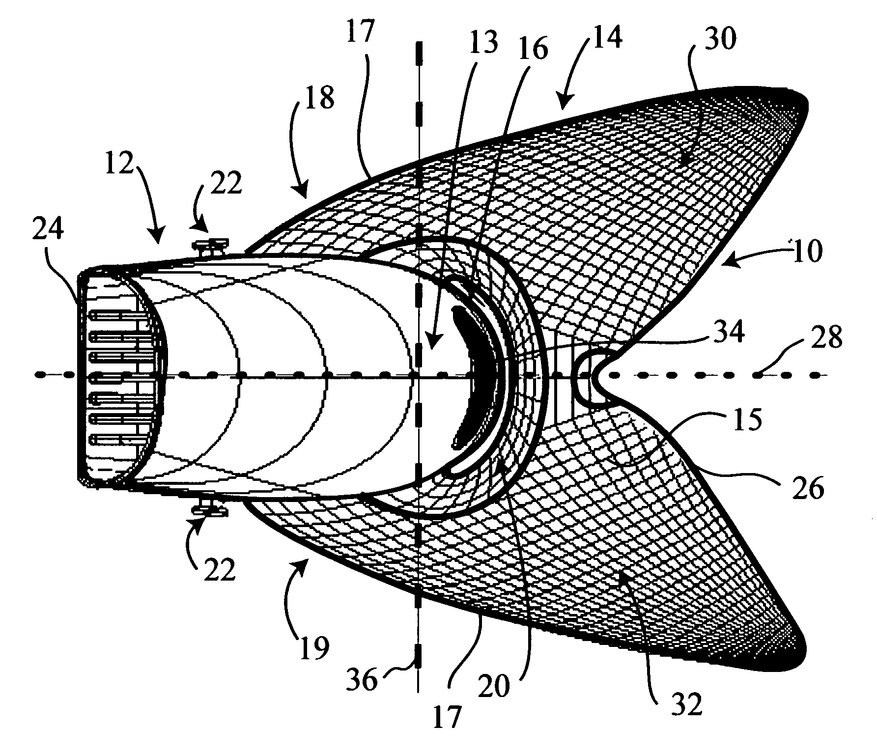
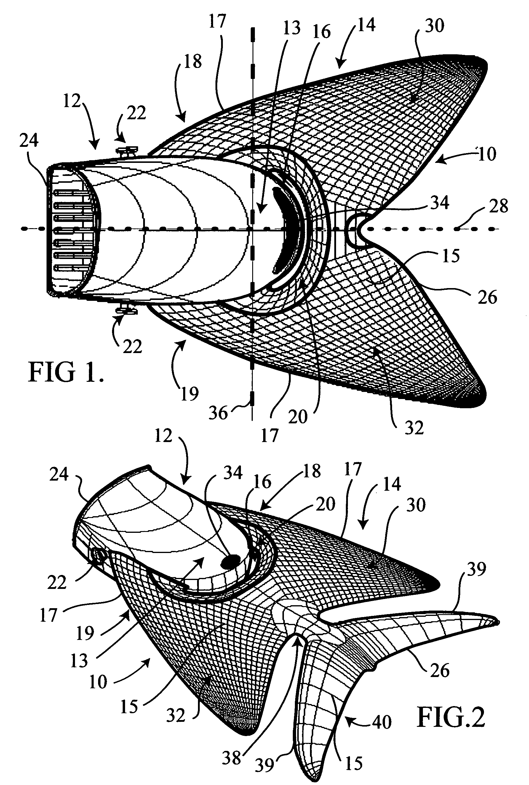
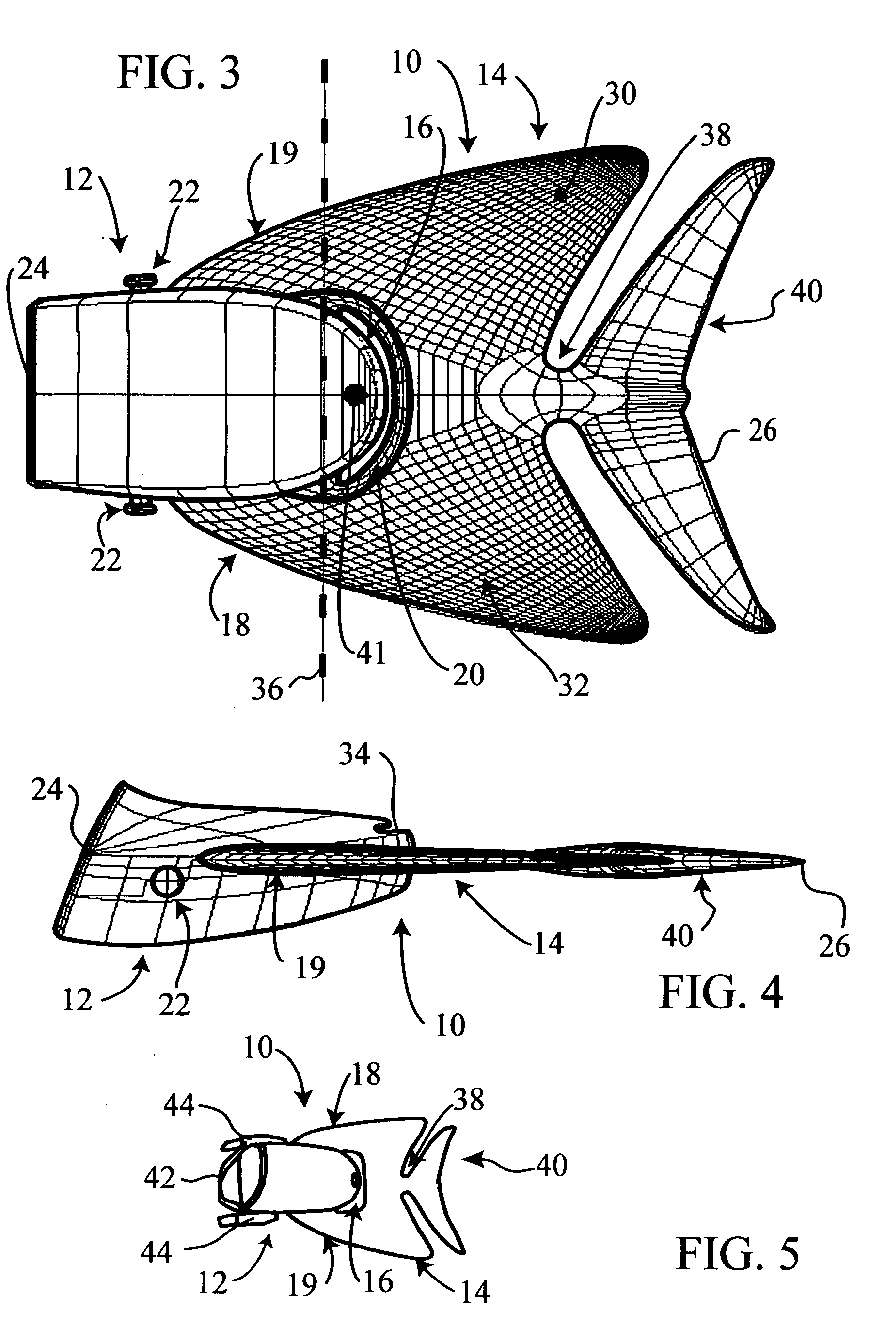
[0044]Referring to FIG. 1, a fin 10 is shown according to a preferred embodiment. Each fin 10 comprises a foot pocket 12, a blade 14 with a relief jet aperture 16, a left-side living hinge 18, and a right-side living hinge 19 that are configured to maintain blade 14 in the desired angle of attack for a variety or range of kicking strengths or powers.

[0045]According to a preferred embodiment, foot pocket 12 and blade 14 are integrally molded (e.g., in a single molding operation for improved economics and as well as excellent performance). Alternatively, foot pocket 12 and blade 14 are fused together to form an integral structure. Foot pocket 12 is shown with an open heel and buckle boss 22 for attachment of a conventional set of buckles and heel straps (shown in FIG. 8). Alternatively, foot pocket 12 includes a closed heel instead or any of a variety of conventional designs. Foot pocket 12 is preferably formed of the same material as blade 14 for improved economics as well as great p...


PUM


Abstract

A fin and a method providing thrust from an unusually low drag kick by a swimmer are disclosed. The fin includes a fin for use by a swimmer comprising a foot pocket adapted to receive a foot of the swimmer; a foil shaped blade extending from the foot pocket; composite hydrodynamic flex control framework configured to allow the blade to bend within a narrow range of angles of attack under a wide range of loads while enhancing hydrodynamic performance. The method comprises providing a fin comprising a foot pocket, a foil shaped blade, an aperture, and two living hinges positioned adjacent to foot pocket. The method also comprises bending the blade relative to the foot pocket about an axis that is nearer the heel of the swimmer to reduce centrifugal forces while controlling the bending of the blade by providing living hinges formed to increase resistance as kicking power increases. This method additionally allows low drag kicking by a swimmer that is similar to walking in place with the swimmer's feet staying within the swimmer's slip stream.

Description

CROSS REFERENCES TO RELATED APPLICATIONS[0001]This invention draws upon provisional application number 60,864,459 filed Nov. 6, 2006.STATEMENT REGARDING FEDERALLY SPONSORED RESEARCH OR DEVELOPMENT[0002]This invention is not related to a federally sponsored research or development project.THE NAMES OF THE PARTIES TO A JOINT RESEARCH AGREEMENT[0003]This invention is not the output of a joint research action or agreement.REFERENCES TO APPENDICES ON A COMPACT DISC AND AN INCORPORATION-BY-REFERENCE OF THE MATERIAL ON THE COMPACT DISC[0004]This application does not include compact discs or related files.FIELD OF THE INVENTION[0005]The present invention relates to a swim fin, comprising a seat for the foot, the so-called foot pocket and a propelling blade (or propelling blade and propelling tail fin) with an advanced design with improved control of the bending of the blade through the formation a relief jet aperture in a portion of the blade of the swim fin that surrounds and frees the toe...

Claims


Application Information

Patent Timeline
IPC IPC(8): A63B31/08
CPCA63B31/11
Inventor MELIUS, JOHN DAVID
Owner MELIUS JOHN DAVID
Why Eureka
Eureka Blog
Learn More