Invasive Distracter

a distractor and invasive technology, applied in the field of invasive distractors, to achieve the effect of free working area

Inactive Publication Date: 2008-05-08
ROLD ORLANDO +1
View PDF7 Cites 20 Cited by
  • Summary
  • Abstract
  • Description
  • Claims
  • Application Information

AI Technical Summary

Benefits of technology

[0014]The object of the present invention is to improve an invasive distractor of the type mentioned above in such a way that the advantages of the known distractors are maintained. The appliance makes it possible to offer the operating surgeon a free working area and is also not in the best area for the imaging by the X-ray camera, and it also allows the relative angle of the two bones forming the joint to be changed rapidly and with precision during the intervention, and the operating surgeon can at all times control the applied force necessary for the distraction.

Problems solved by technology

The appliance makes it possible to offer the operating surgeon a free working area and is also not in the best area for the imaging by the X-ray camera, and it also allows the relative angle of the two bones forming the joint to be changed rapidly and with precision during the intervention, and the operating surgeon can at all times control the applied force necessary for the distraction.

Method used


Image

  • Invasive Distracter
  • Invasive Distracter
  • Invasive Distracter

Examples


Embodiment Construction

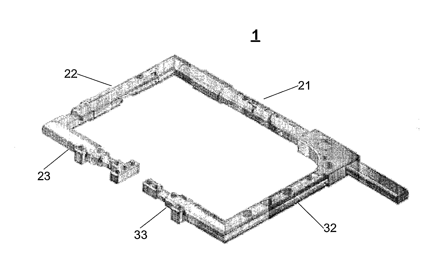
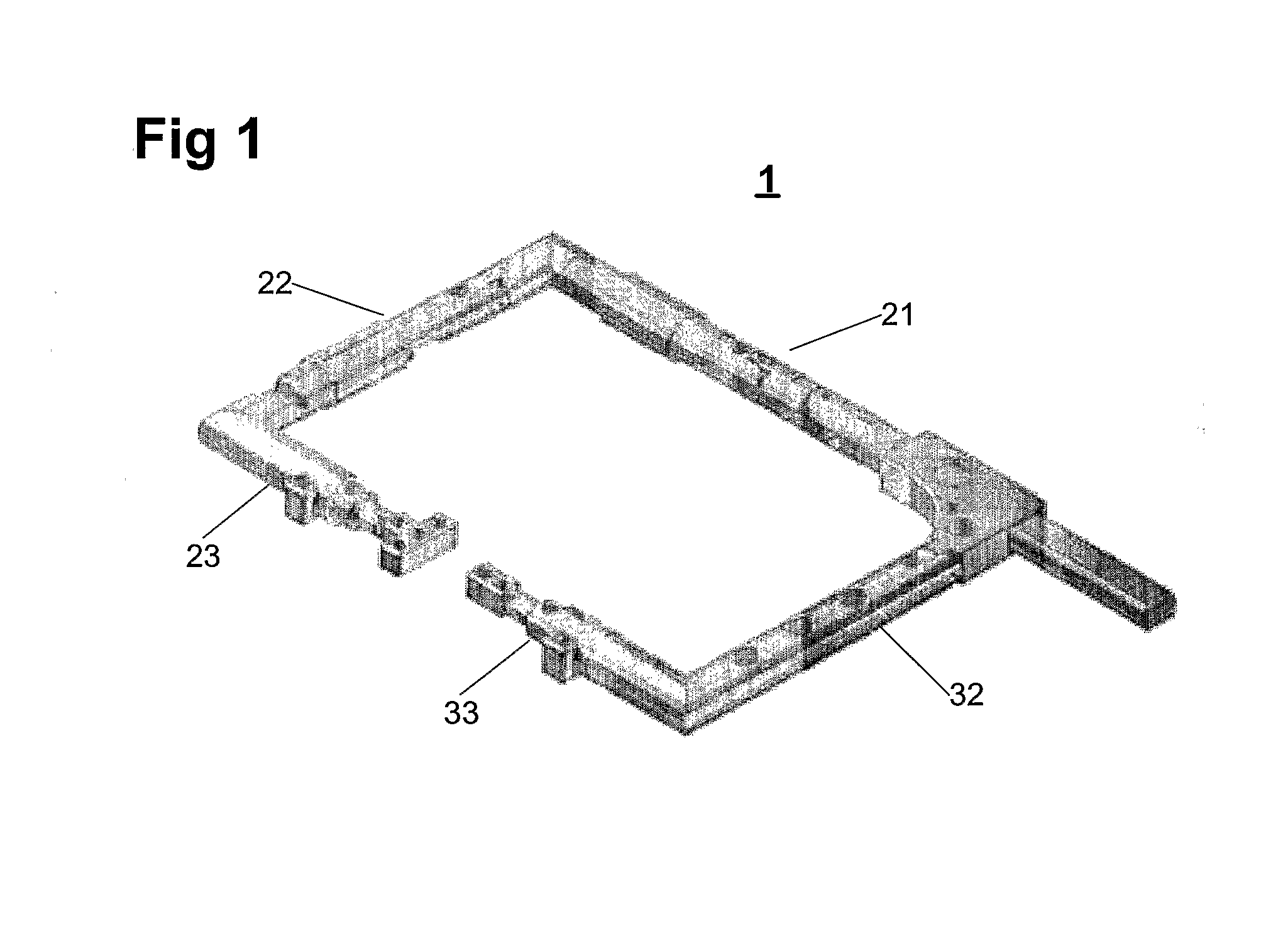
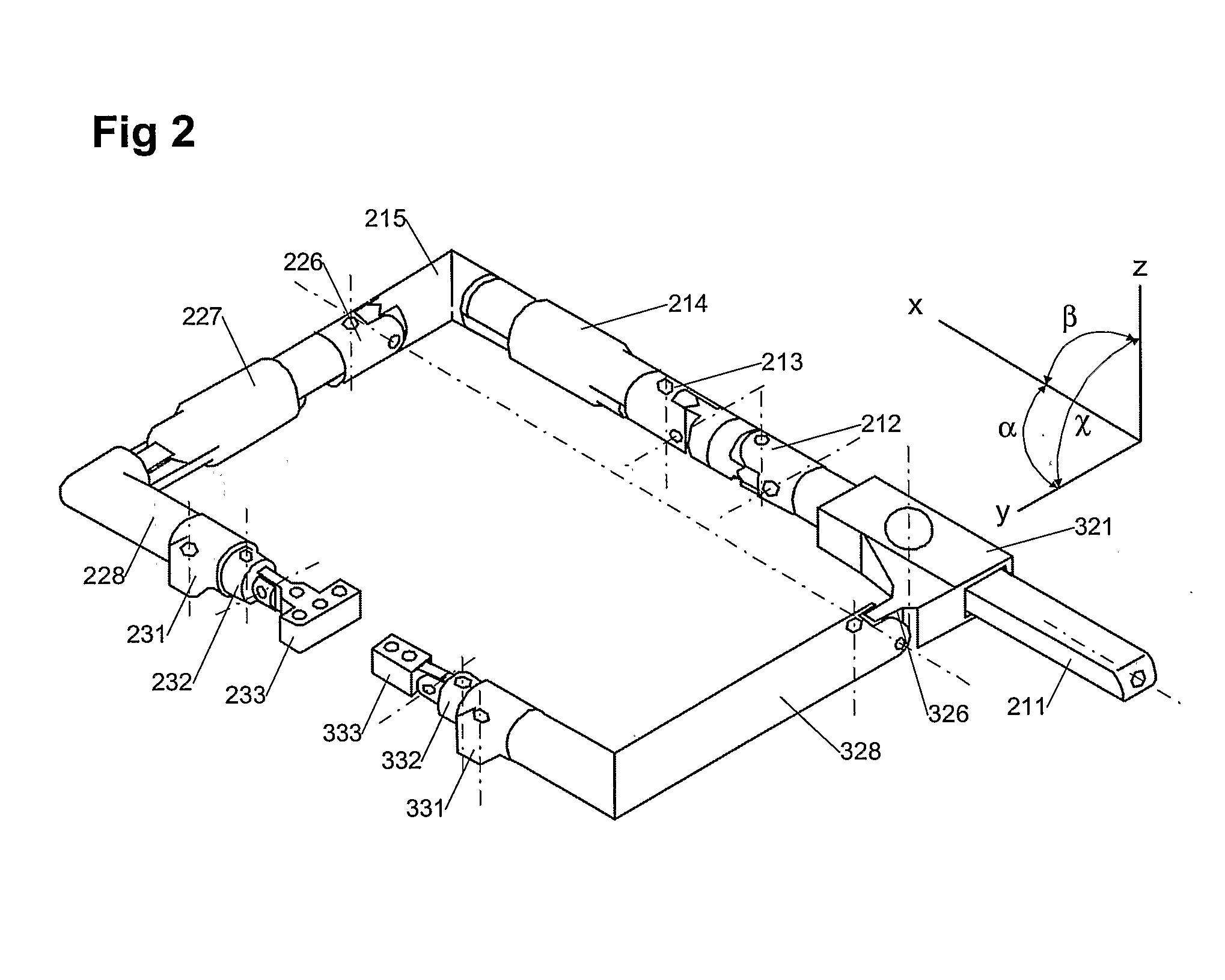
[0034]To describe the invasive distractor 1 as fully as possible, the following description deals with the design and mechanical details of the invasive distractor 1 and also with the practical use thereof. The invasive distractor 1 according to the invention consists (FIGS. 1, 2 and 3) of the following parts. The two main components, namely base 2 (FIG. 4) and slide 3 (FIG. 5), are connected to one another (FIG. 3) by the runner 321 of the slide 3 being mounted with a shape fit on the guide part 211 so as to be longitudinally movable thereon and secure against twisting. To be able to control the longitudinal movement, a thread 219 is arranged on the guide part 211. A nut 319 is mounted on the runner 321 so as to be rotatable thereon, but fixedly connected thereto. By turning the nut 319, the latter moves on the thread 219 and, as a result, the runner 321 moves on the guide part 211 by the distance set by the thread pitch and defined by the extent by which the nut 319 is turned.

[003...


PUM


Abstract

An invasive distractor is proposed that has a form comparable to a conventional C-clamp or screw clamp. It permits spatially targeted positioning of two bones, so that the joint connecting these bones can be spread by means of distraction during an intervention, thereby creating the space needed to perform diagnosis and/or interventions by means of arthroscopic methods. The appliance is composed of a base (2) and of a slide (3) which can be displaced relative to one another in a controlled manner and secure against twisting. The base (2) and the slide (3) comprise various devices, such as worm gear, rotary gear and expansion gear, to ensure that the distraction of the two bones can be performed in a spatially exact manner adapted to the particular requirements.

Description

FIELD OF THE INVENTION[0001]The present invention relates to an invasive distractor.BACKGROUND OF THE INVENTION[0002]The methods of distraction and compression of bones are widely known in orthopaedics. In surgery of the jaw, these methods are used to correct the positions of the teeth and jaw. In cases of angle defects or length defects caused by congenital malformations or by incorrectly fused bone fractures, these methods are applied using the appropriate devices. Devices for corrections of individual bones are described, for example, in EP 0 699 419 A and in EP 0 858 781 A. Such devices are also used in accident and emergency surgery. They are used mainly as so-called fixators, in order to bring the two parts of a broken bone into the correct position for fusion and also to hold them in this position.[0003]Another use, to which the present invention relates, is for the distraction of joints. To treat tissues in proximity to joints and within joints, distraction is often required...

Claims


Application Information

Patent Timeline
Patent Type & Authority Applications(United States)
IPC IPC(8): A61B17/58A61B17/02A61B17/64A61B17/66
CPCA61B17/0206A61B17/025A61B2017/0275A61B17/6441A61B17/66A61B17/6425
Inventor DA ROLD, ORLANDOSADRI, HASSAN
Owner ROLD ORLANDO
Why Eureka
Try Eureka