Spinal cross connectors

a cross connector and spine technology, applied in the field of spine fixation devices, can solve the problems of increased manufacturing costs, difficult fixation of the cross connector to the spinal rod, and mounting difficulties of the cross connector

Active Publication Date: 2008-05-08
DEPUY SYNTHES PROD INC
View PDF98 Cites 110 Cited by
  • Summary
  • Abstract
  • Description
  • Claims
  • Application Information

AI Technical Summary

Benefits of technology

[0014]In other aspects, a spinal cross connector is provided having an elongate body with opposed first and second ends and opposed top and bottom surfaces. First and second recesses are formed in the bottom surface adjacent to the first and second ends of the elongate body. The first and second recesses are oriented to enable the elongate body to be simultaneously top-loaded onto first and second spinal fixation elements. The cross connector can also include first and second bores formed in the top surface of the elongate body and effective to receive first and second locking mechanisms for locking first and second spinal fixation elements within the first and second recesses. The first and second bores can have longitudinal axes that are substantially parallel to one another and that are substantially parallel to an axis of loading the elongate body onto first and second spinal fixation ...

Problems solved by technology

While current spinal cross connectors have proven effective, difficulties have been encountered in mounting the cross connectors, and maintaining them in a desired position and orientation with respect to the spinal rod, or other spinal fixation device to which they are attached.
In particular, the clamp assemblies o...

Method used


Image

  • Spinal cross connectors
  • Spinal cross connectors
  • Spinal cross connectors

Examples


Embodiment Construction

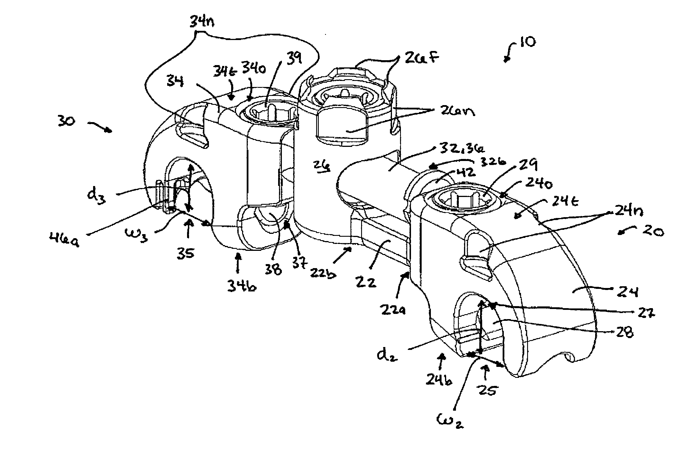
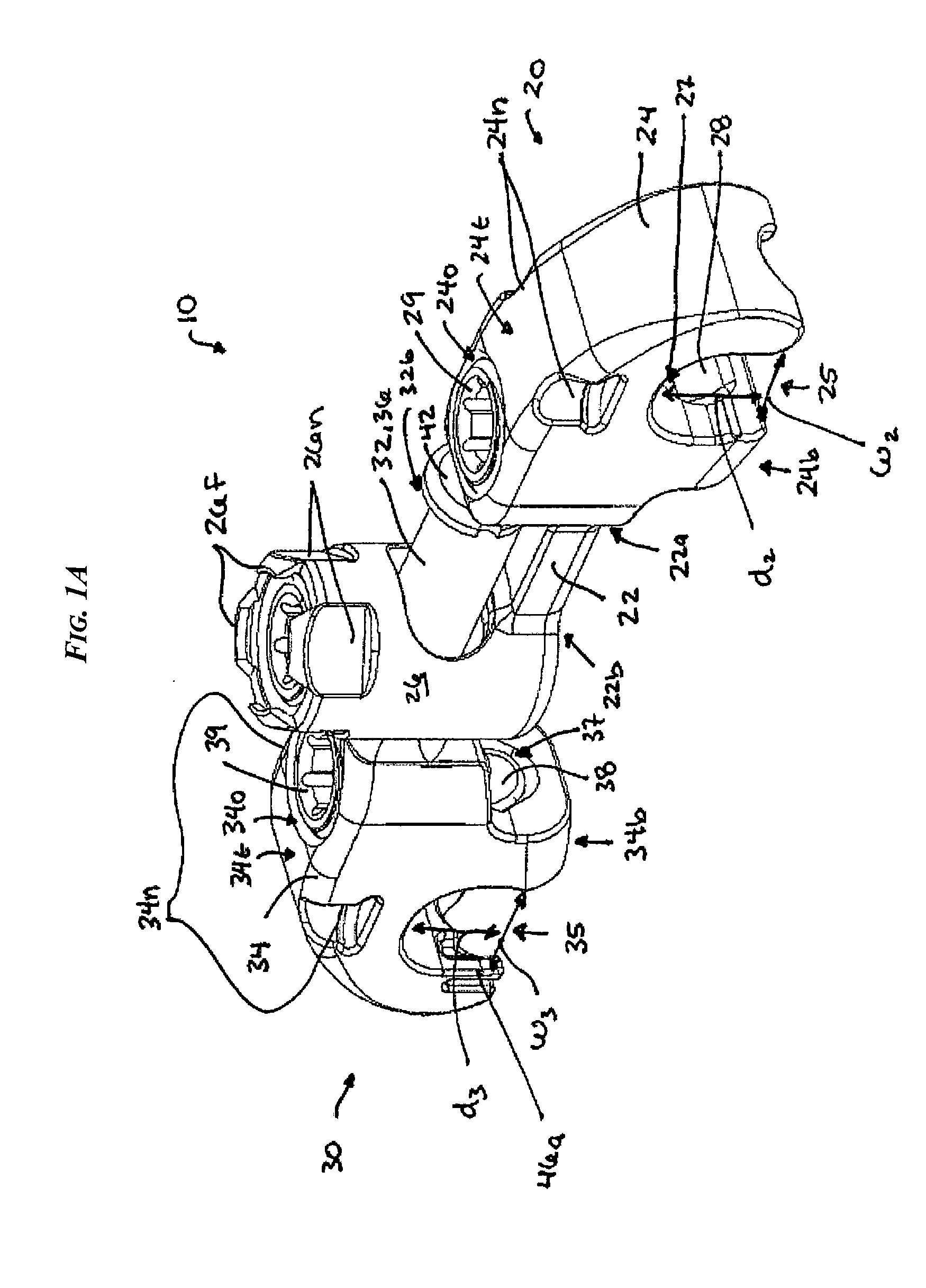
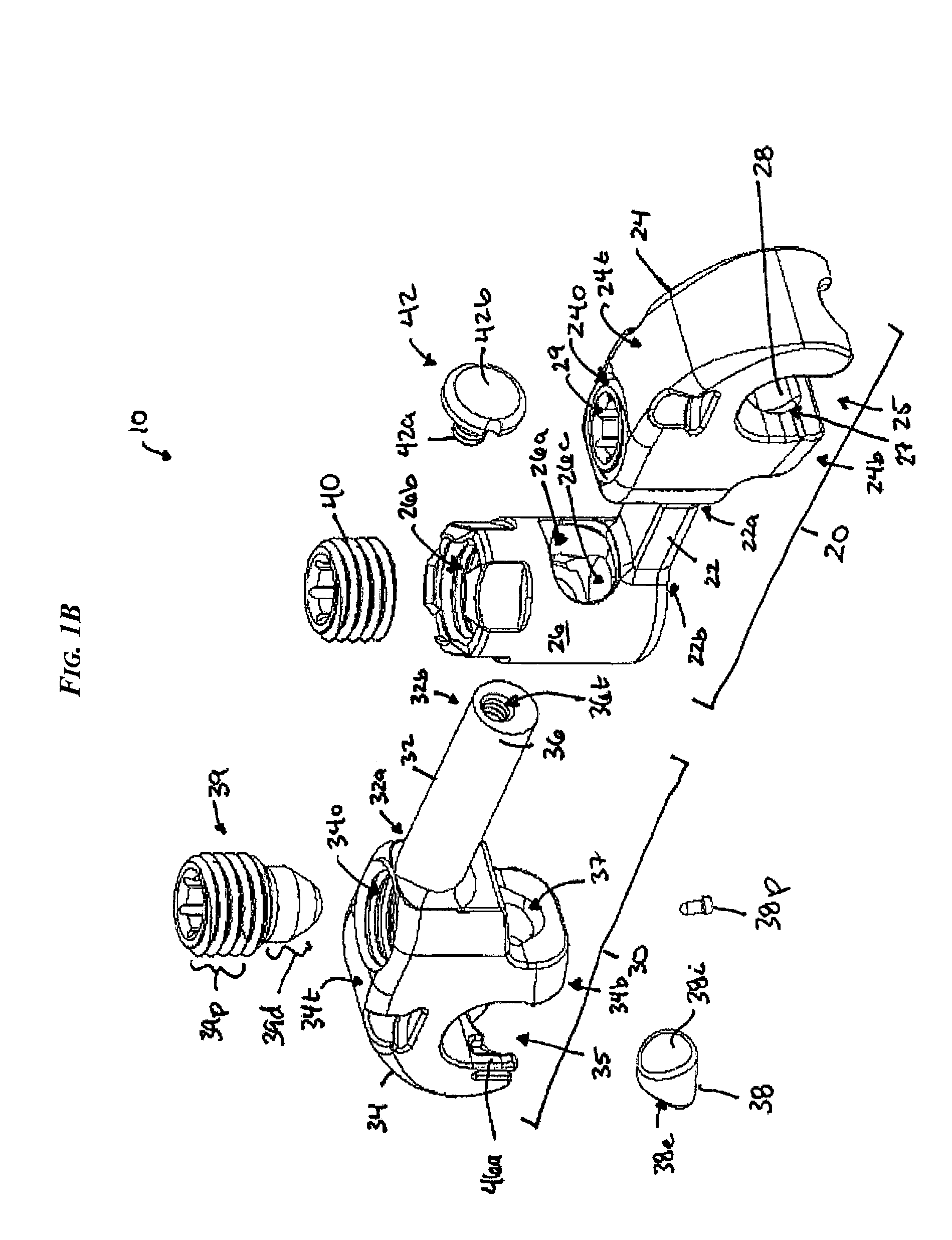
[0056]Certain exemplary embodiments will now be described to provide an overall understanding of the principles of the structure, function, manufacture, and use of the devices and methods disclosed herein. One or more examples of these embodiments are illustrated in the accompanying drawings. Those of ordinary skill in the art will understand that the devices and methods specifically described herein and illustrated in the accompanying drawings are non-limiting exemplary embodiments and that the scope of the present invention is defined solely by the claims. The features illustrated or described in connection with one exemplary embodiment may be combined with the features of other embodiments. Such modifications and variations are intended to be included within the scope of the present invention.

[0057]The present invention generally provides various methods and devices for connecting spinal fixation elements, such as spinal rods, implanted in a patient's spinal column. In general, e...


PUM


Abstract

Various methods and devices are provided for connecting spinal fixation elements, such as spinal rods, implanted in a patient's spinal column. In particular, various spinal cross connectors are provided for connecting to one or more spinal fixation elements implanted in a patient's spine. The cross connectors can have a variety of configurations, including a fixed or adjustable length, as well as various features that allow certain portions of the cross connectors to be angularly oriented.

Description

FIELD OF THE INVENTION[0001]The present invention relates to spinal fixation devices, and in particular to a cross connector for connecting spinal fixation elements, such as spinal fixation rods, implanted in a patient's spinal system.BACKGROUND OF THE INVENTION[0002]Spinal fixation devices are used in orthopedic surgery to align and / or fix a desired relationship between adjacent vertebral bodies. Such devices typically include a spinal fixation element, such as a relatively rigid fixation rod, that is coupled to adjacent vertebrae by attaching the element to various anchoring devices, such as hooks, bolts, wires, or screws. Alternatively, two rods can be disposed on the lateral or anterior surface of the vertebral body in a substantially parallel relationship. The fixation rods can have a predetermined contour that has been designed according to the properties of the target implantation site, and once installed, the rods hold the vertebrae in a desired spatial relationship, either ...

Claims


Application Information

Patent Timeline
IPC IPC(8): A61B17/58
CPCA61B17/7049A61B17/7052
Inventor MICHIELLI, MICHAEL CARLCORMIER, PHILIP A.QUINTANILHA, ERNESTSTALABOIN, JOSEPH T.BRIDEAU, HOLLY R.
Owner DEPUY SYNTHES PROD INC
Why Eureka
Try Eureka