Drawer air-filter device and inlet assembly having such a device

a technology of air-filter device and inlet assembly, which is applied in the direction of combination device, filtration of dispersed particles, using liquid separation agent, etc., can solve the problems of sealing risk being damaged and/or incorrectly positioned

Active Publication Date: 2008-05-15
MARK IV SYST MOTEURS USA
View PDF10 Cites 52 Cited by
  • Summary
  • Abstract
  • Description
  • Claims
  • Application Information

AI Technical Summary

Benefits of technology

[0015]For this purpose, the present invention relates to an air-filter device of the type previously described characterised in that the respective inclinations of the contact surfaces in mutual sliding bearing of the support and compression bodies are defined in such a way that the forced stress position is achieved by displacement of the compression body in the direction of extraction and in that the control device stresses the supporting body and / or the casing in order to achieve the displacement of the compression body in a forced stress position, at least at the end of displacement.

Problems solved by technology

However, in this construction, the seal risks being damaged and / or incorrectly positioned taking into account its displacement under pressure in relation to the casing.
Nevertheless, both of the above-mentioned constructions of air-filter have one major drawback, namely that sealing by compression is achieved by pushing in the direction of introduction of the filtering body, this push being transmitted, chiefly at the end of the introduction movement, when the force of the push and often the inertia of movement are at their maximum, to the casing and by the latter to its fixing points and to the parts that are connected to it.

Method used


Image

  • Drawer air-filter device and inlet assembly having such a device
  • Drawer air-filter device and inlet assembly having such a device
  • Drawer air-filter device and inlet assembly having such a device

Examples


first embodiment

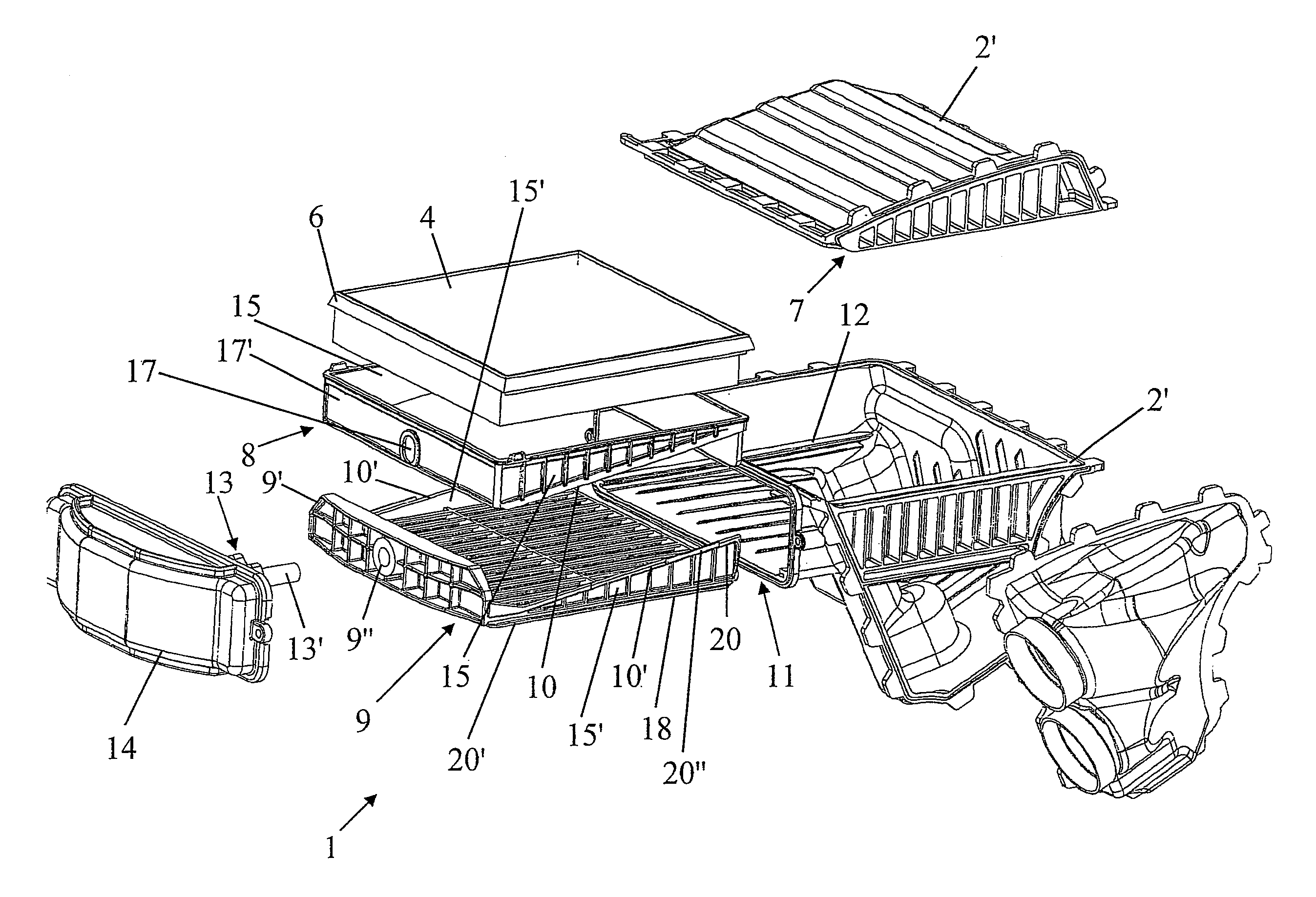
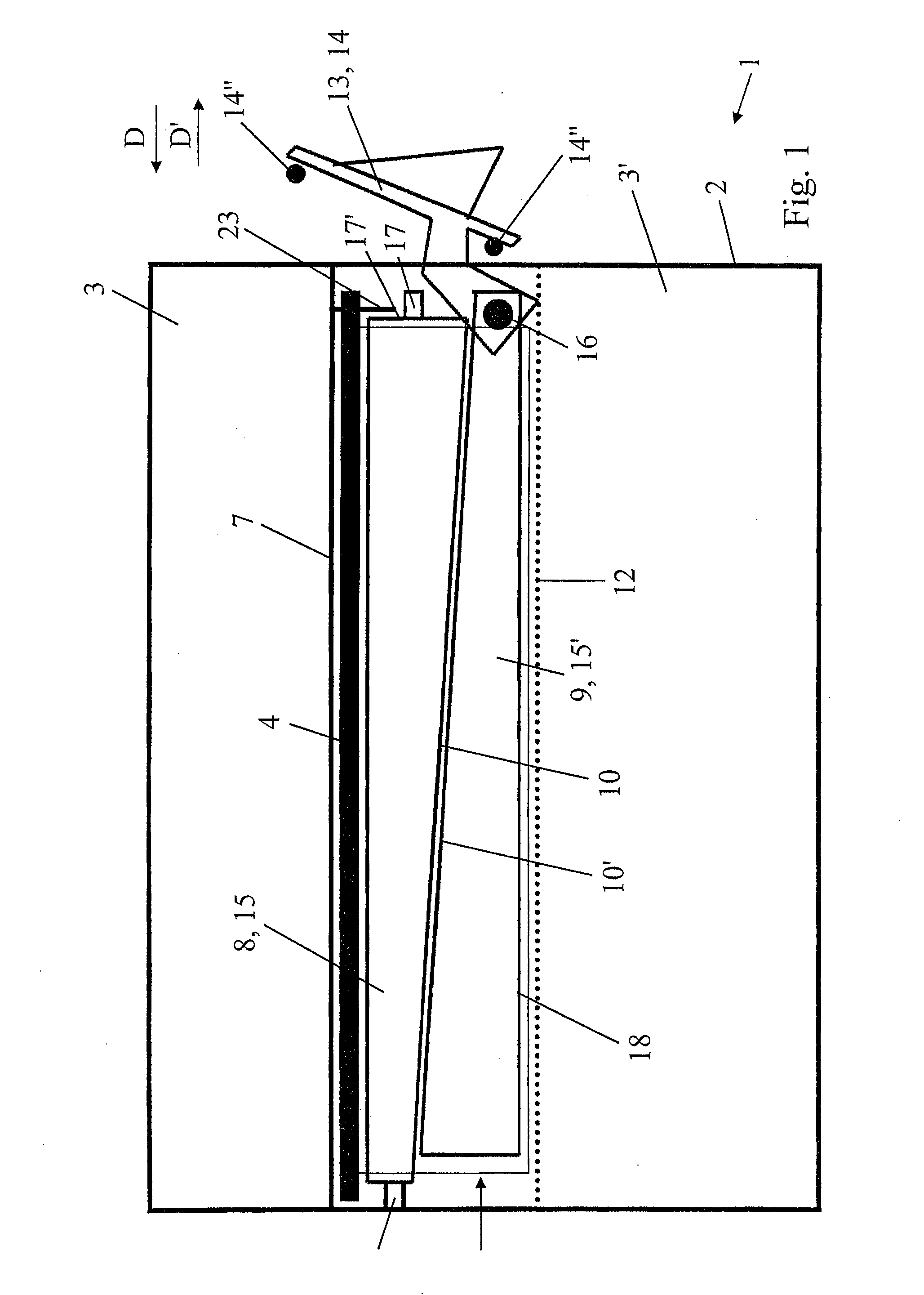
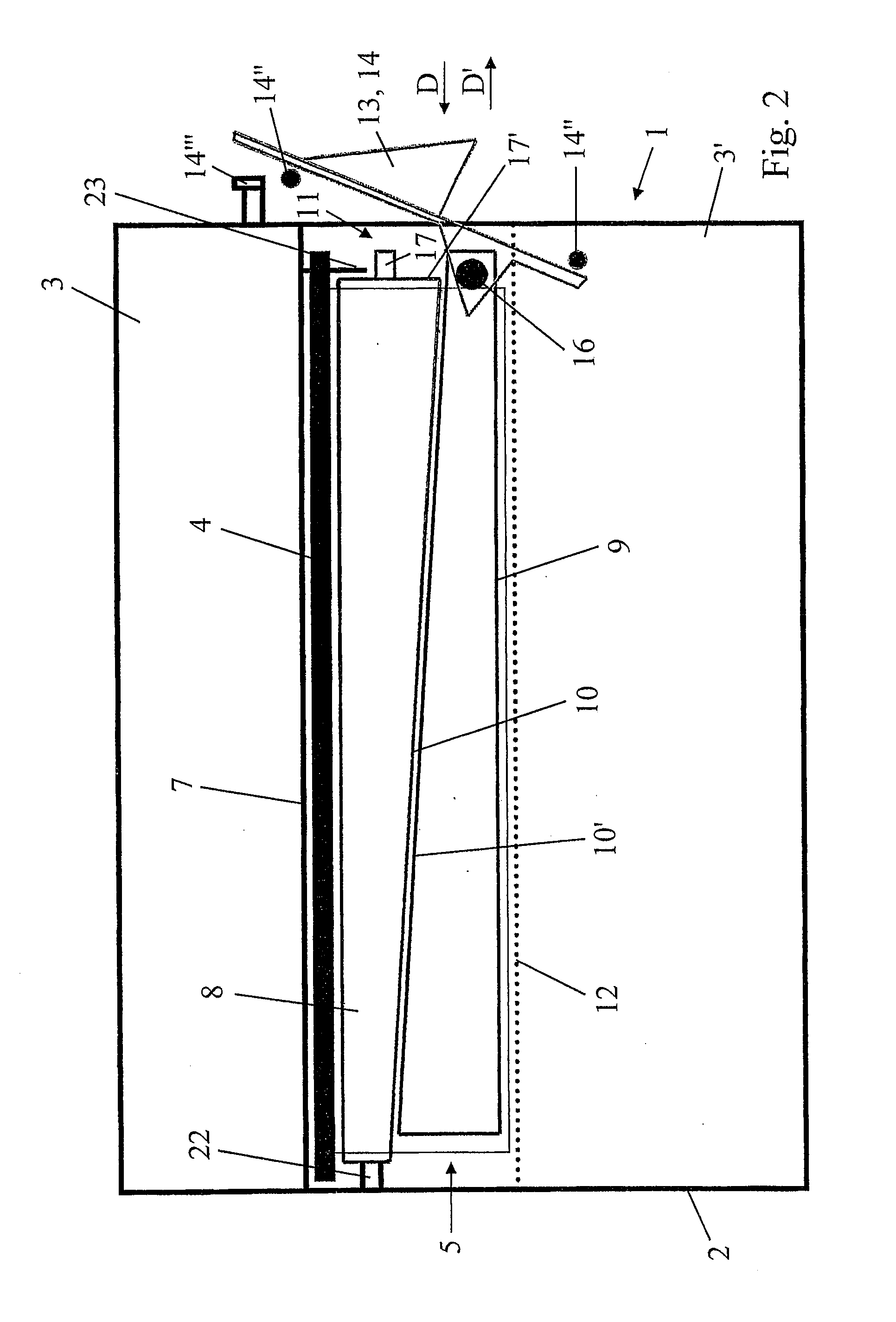
[0032]According to the invention, shown in FIGS. 1 and 2 of the accompanying drawings, the control device 13 consists of the cover itself 14, the latter being made in the form of a pivoting cover, and connected to the compression body 9 by a pivot connection 16 so that lowering the said cover 14 towards its position of blocking the side access opening 11 causes a sliding of the compression body 9 towards the stress position, the said pivoting cover 14 being lockable in the blocking position.

[0033]The passage freed up by the cover 14 in the open position will be sufficient to enable the extraction of the supporting body 8 / filtering body 4 assembly, without the need to extract the compression body 9 as well.

[0034]The said cover 14 is also fitted with a seal or a plurality of portions of a seal 14″ making it possible to seal off the access opening 11 when the said cover 14 is in the closed position. In this position, it is also locked by locking means 14′″ or removable means of connect...

second embodiment

[0038]According to the invention, shown in FIGS. 3A, 3B, 6 and 7 of the accompanying drawings, the control device 13 may consist of a traction device connected to the compression body 9, the said device 13 bearing on the cover 14, on the supporting body 8 and / or on the casing 2, at least at the end of the movement of the compression body 9 in the forced stress position.

[0039]Advantageously, when the device 13 bears on the cover 14, and for example passes through the latter, it will also contribute to holding in place and achieving the seal at the opening 11 (compression of the cover seal 14″.

[0040]As a variant, within the scope of this second embodiment, the control device 13 may also be built into the cover 14, forming a distinctive part of the said cover (FIG. 3B).

[0041]The control device 13 may also be located beneath the cover or cap 14, being covered by the latter (FIGS. 6 and 7).

[0042]By way of preferred examples, the control device 13 may be maneuvered progressively, for exam...


PUM

PropertyMeasurementUnit
volumeaaaaaaaaaa
resistanceaaaaaaaaaa
areaaaaaaaaaaa

Abstract

An air-filter device for a motor vehicle, having a casing and a filtering body separating the clean and dirty compartment, and also having a supporting body for the filtering body and a compression body designed to co-operate mechanically with the supporting body, these bodies being mounted in the manner of sliding drawers in an intermediate mounting compartment; the contact surfaces in mutual sliding bearing of the support and compression bodies are inclined in such a way that the forced stress position leading to a compression of the seal of the filtering body is achieved by displacement of the compression body in the direction of extraction and in that the control device, bringing about this displacement, stresses the supporting body and/or the casing in order to achieve the displacement of the compression body in a forced stress position, at least at the end of displacement.

Description

[0001]The present invention concerns the field of equipment for motor vehicles with internal combustion engines, particularly the air-inlet equipment of such vehicles, and relates to an air-filter device and an air-inlet assembly having such a device.BACKGROUND OF THE INVENTION[0002]Currently, air-filter devices for the above-mentioned vehicles generally comprise, basically, on the one hand, a casing, in one or more parts, defining a volume or so-called clean compartment receiving the filtered gases and a volume or so-called dirty compartment receiving the gases to be filtered, and, on the other hand, a filtering body separating the two above-mentioned compartments, installed in an intermediate mounting area or compartment and having a peripheral seal that comes to be applied against an edge or circumferential similar internal step of the casing, which delimits the said intermediate compartment in relation to the clean compartment.[0003]The peripheral seal is usually insert-moulded ...

Claims


Application Information

Patent Timeline
Patent Type & Authority Applications(United States)
IPC IPC(8): B01D46/00
CPCB01D46/0005B01D46/0006B60H3/0616F02M35/024F02M35/0203
Inventor GERMAIN, LAURENTCOTTET, FRANCOISWINKELMULLER, HUGUES
Owner MARK IV SYST MOTEURS USA
Why Eureka
Try Eureka