Selectively configurable relay

a relay and configurable technology, applied in the field of relays, can solve the problems of often proving disadvantageous solutions for relays

Inactive Publication Date: 2008-05-15
SIEMENS HEATHCARE GMBH
View PDF9 Cites 11 Cited by
  • Summary
  • Abstract
  • Description
  • Claims
  • Application Information

AI Technical Summary

Benefits of technology

[0007]An object of the present invention is to provide a relay with which various swi

Problems solved by technology

If the switching functions are more complex, however, (for example in radio-frequency power engineering), it is frequently necessary to use various available relays that must be interconnected and mounted in a more c

Method used


Image

  • Selectively configurable relay
  • Selectively configurable relay
  • Selectively configurable relay

Examples


Embodiment Construction

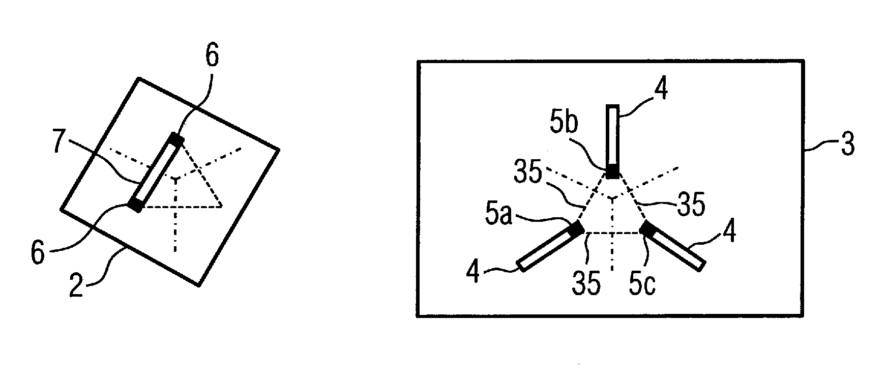
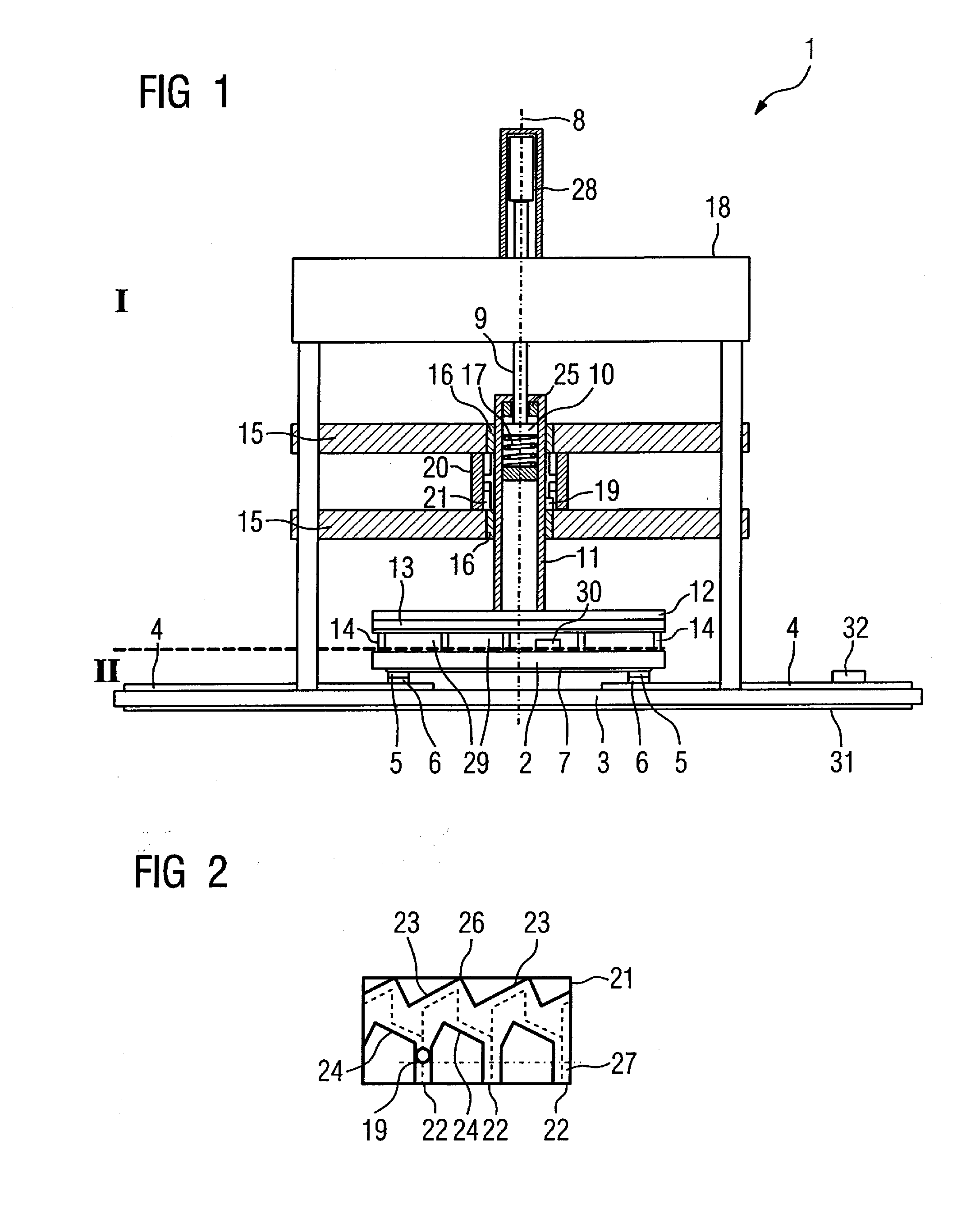
[0092]FIG. 1 shows a cross-section through an inventive relay 1. It has a mechanical actuator primarily arranged in region I with which a second circuit board 2 can be moved against a first circuit board 3 such that the second circuit board can occupy various contact positions.

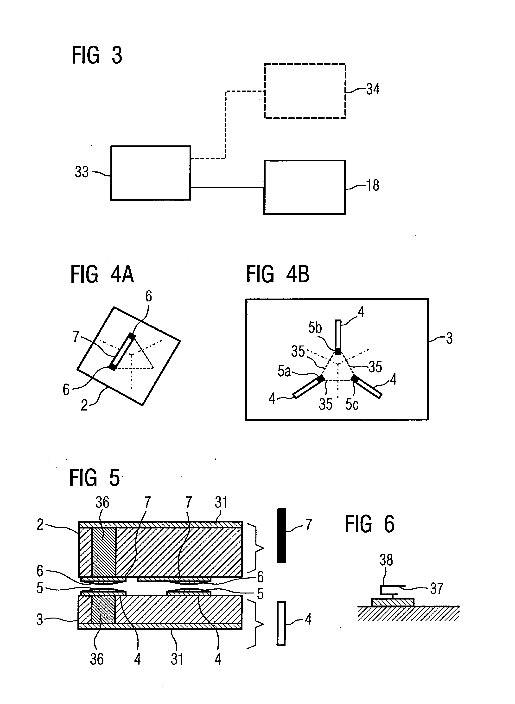
[0093]The first circuit board 3 has first conductor traces 4 that are electrically connected with first contacts 5. In one contact position the second circuit board 2 is pressed against the first circuit board 3 such that second contacts 6 of the second circuit board 2 (which are in turn electrically connected with second conductor traces 7) come in contact with selected first contacts 5 such that an electrical connection is provided. Different first contacts 5 contact different second contacts 6 in different contact positions.

[0094]The entire electrical switching function is accordingly defined by the two circuit boards 2 and 3 that are associated with the region II.

[0095]The mechanical actuator in region I a...


PUM


Abstract

A relay, in particular for radio-frequency applications, has at least one first contact electrically connected with a first conductor trace, the first contact in a contact position can be selectively electrically connected by a mechanical actuator with at least two second contacts electrically connected with at least one second conductor trace. The relay has a spatially fixed first circuit board with the first contact and the first conductor trace and a second circuit board with the second contacts and the second conductor trace that can be moved against the first circuit board into various contact positions by the mechanical actuator.

Description

BACKGROUND OF THE INVENTION[0001]1. Field of the Invention[0002]The present invention concerns a relay, in particular for radio-frequency applications, of the type having at least one first contact electrically connected with at least one first conductor trace printed conductor, the first contact, in a contact position, being selectively connectable by a mechanical actuator with at least two second contacts that are electrically connected with at least one second conductor trace.[0003]2. Description of the Prior Art[0004]Relays are frequently used in radio-frequency engineering (in particular in power applications) as robust and technically less complicated components. As a single-unit solution for specific functionalities, relays are available in various forms that for the most part perform quite simple switching functions.[0005]If the switching functions are more complex, however, (for example in radio-frequency power engineering), it is frequently necessary to use various availab...

Claims


Application Information

Patent Timeline
IPC IPC(8): H01H67/06H01H19/20
CPCH01H1/2041H01H1/5805H01H19/563H01H2003/268H01H50/18H01H50/546H01H50/548H01H19/585
Inventor RAUH, GEORG
Owner SIEMENS HEATHCARE GMBH
Why Eureka
Try Eureka