
Artificial reef anchor structure

a technology of artificial reefs and anchor structures, applied in the field of anchors, can solve the problems of predatory fish, limiting access to larger fish, and none of the above patents functions as an anchor for mooring floating vessels or structures, and none of the above patents can in any respect serve the function of an anchor for anything

Inactive Publication Date: 2008-05-15
HARDISON STEWART
View PDF14 Cites 19 Cited by
  • Summary
  • Abstract
  • Description
  • Claims
  • Application Information

AI Technical Summary

Benefits of technology

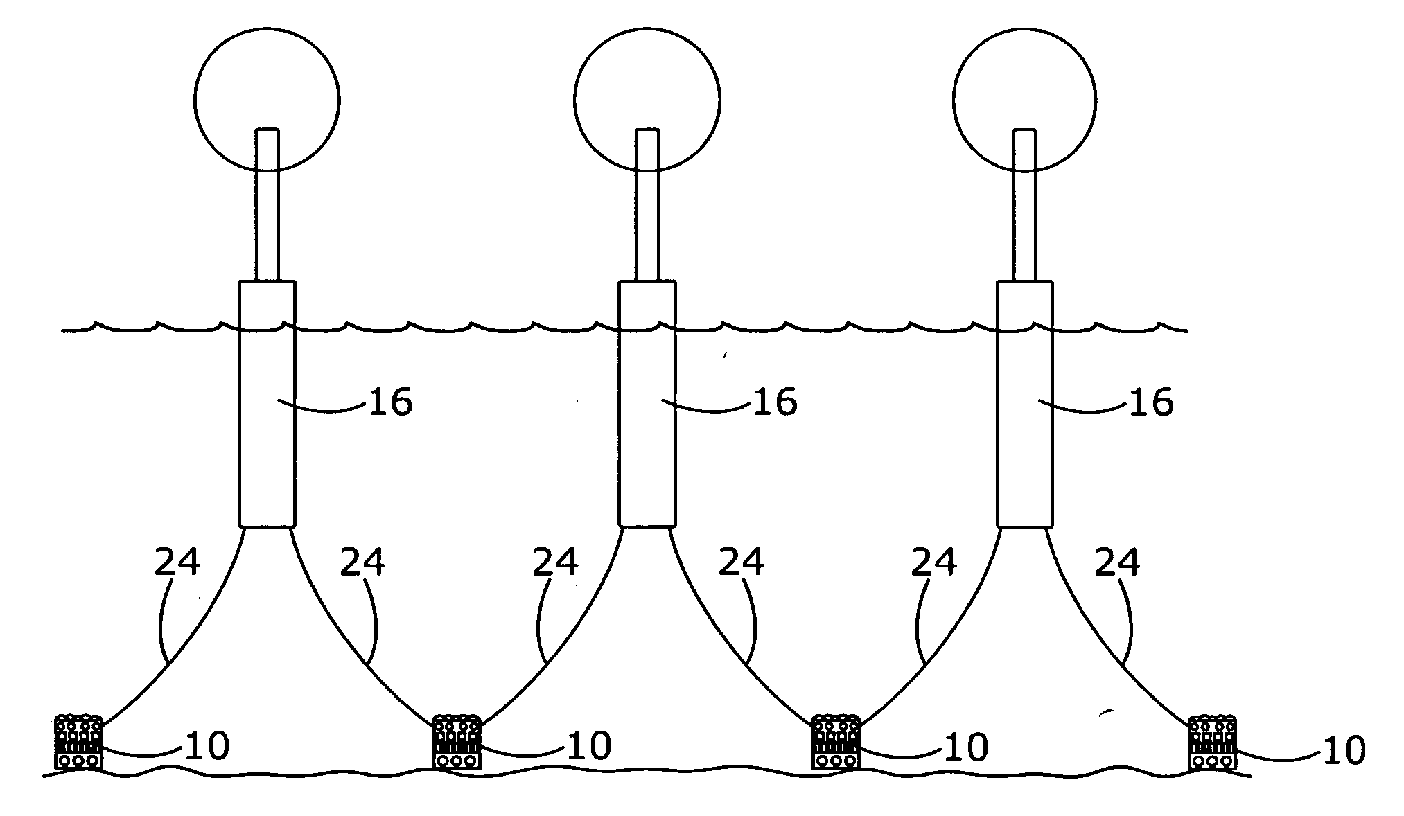
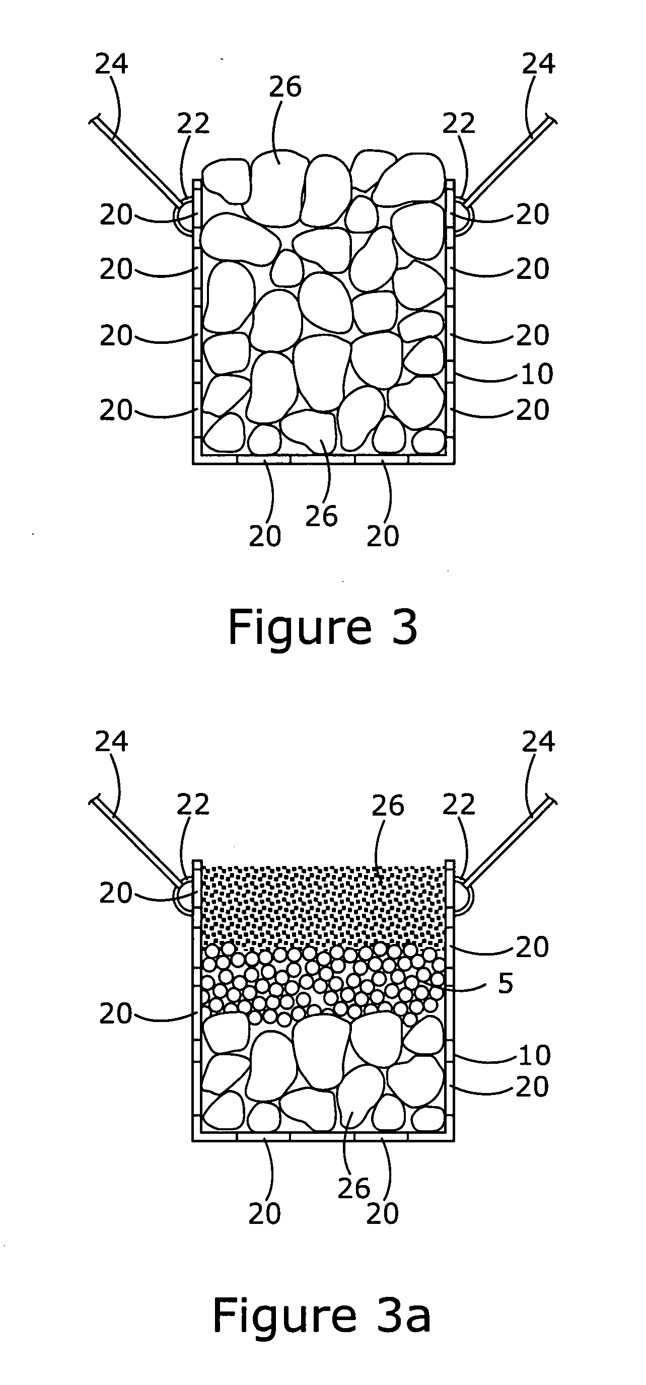
[0018]The invention provides a container for underwater placement on a sea, lake or river bottom. The container has openings in the sides, top and bottom and is filled with ballast of large boulders or other materials. The openings allow water currents, as well as marine organisms, to pass freely therethrough. Over time, marine organisms colonize the cavity areas of the ballast, thus utilizing the habitat within the container as an artificial reef. One or more hitch points are provided on the container for attaching mooring lines, thereby allowing the container to serve as an anchor for ships and other floating vessels.

Problems solved by technology

The interior spaces of the structures provide sanctuary to small fish and other organisms, while limiting access to larger, predatory fish.
While a number of the above cited patents employ means to hold them in place on the marine bottom, none of the above patents functions as an anchor for mooring floating vessels or structures.
In summary, none of the above artificial reefs can in any respect serve the function of an anchor for anything but itself.
Individually, the blocks are transportable by helicopter, but when assembled on the base skid they cumulatively can weigh dozens of tons.
These drag embedded anchors generally require long mooring lines to function effectively.
The above described permanent and portable devices may inadvertently attract marine organisms, as will virtually any object which resides on submerged ground in either freshwater or salt water environment.
While it is well known that such structures attract marine organisms, the underwater components of these structures are not in any sense a “reef,” as they do not have the requisite components of piled rocks, boulders, gravel, concrete modules or crushed coral which create myriad nooks, crannies, ledges, crevices and cavities which both natural and artificial reefs present.

Method used


Image

  • Artificial reef anchor structure
  • Artificial reef anchor structure
  • Artificial reef anchor structure

Examples


Embodiment Construction

[0033]The invention provides an underwater, ballast filled container with openings in the sides, top and bottom. The openings allow water currents, as well as marine organisms, to pass freely therethrough. Over time, marine organisms colonize the cavity areas of the ballast, thus utilizing the container as an artificial reef. One or more hitch points are provided on the container for attaching mooring lines, thereby allowing the container to serve as an anchor.

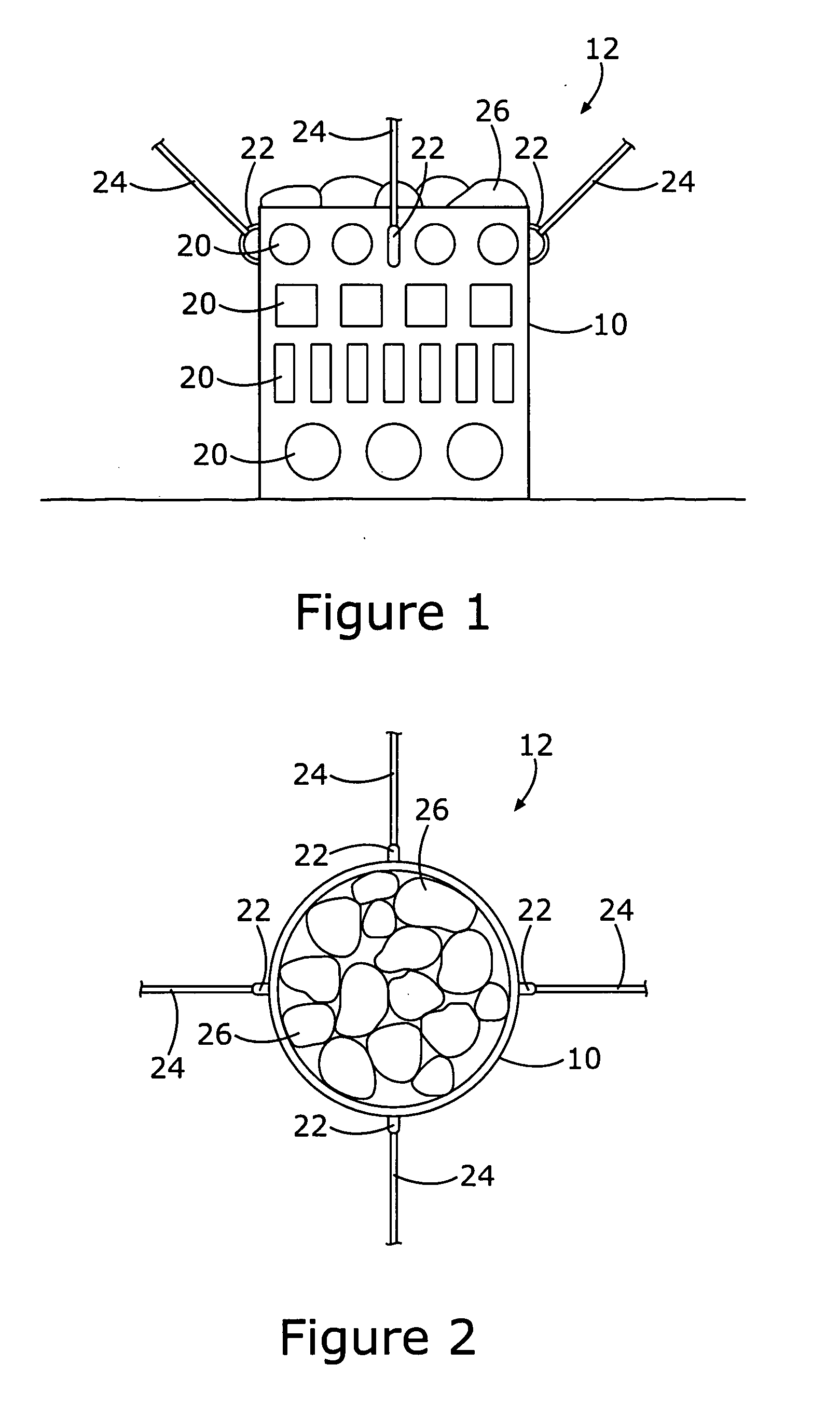
[0034]Referring now to FIGS. 1 through 5a, the artificial reef 12 consists of a container 10 with a plurality of openings 20 and a plurality of mooring rings 22, onto which are attached a plurality of mooring lines 24. Container 10 is filled with ballast 26.

[0035]As best seen in FIG. 2, container 10 is cylindrical, with a plurality of mooring lines 24 radiating outward at 90 degrees spacing from each other. While a circular, or cylindrical, container has certain advantages relating to strength and efficiencies of manufacture, ...


PUM


Abstract

A container for underwater placement on a sea, lake or river bottom. The container has openings in the sides, top and bottom and is filled with ballast of large boulders, cobble, crushed coral, cast concrete modules or other materials. The openings allow water and water currents, as well as marine organisms, to pass freely therethrough. Over time, a wide assortment of marine organisms infiltrate and colonize the nooks, crevices and cavities of the ballast, thus utilizing the habitat as they would an artificial reef. One or more hitch points are provided on the container for attaching mooring lines for ships, boats, floating wind turbines or other floating structures, thereby allowing the artificial reef to anchor such structures.

Description

FIELD OF THE INVENTION[0001]The invention relates to anchors and, more particularly, to a specialized anchor that provides an artificial reef habitat that is attractive to a wide variety of underwater organisms.BACKGROUND OF THE INVENTION[0002]Artificial reefs are found commonly around the world. Some are constructed to protect harbors or beaches from wind, wave or tidal forces. These types of reefs are often constructed of large, boulder sized stones or concrete modules that are cast in a variety of shapes and sizes.[0003]Reefs designed for protection purposes generally extend above the water line so as to deflect the forces of wind, wave or tide. These protective artificial reefs can be of any size or shape; sometimes they are circular, semi-circular, curved or straight. When they are constructed to abut a shoreline, they are sometimes called a break wall. When they extend from the shoreline out into open water, they are sometimes called a jetty. Whatever they are called, they are...

Claims


Application Information

Patent Timeline
IPC IPC(8): E02B3/04
CPCB63B21/29Y02B10/30E02B3/24E02B3/046
Inventor HARDISON, STEWART
Owner HARDISON STEWART
Learn More