

Functional unit positioning device and image forming apparatus
a positioning device and functional unit technology, applied in the direction of pile separation, furniture parts, transportation and packaging, etc., can solve the problems of inaccurate positioning of function units, reduced operating force for inserting or removing functional units, and far too high operating force required in conventional devices to be considered acceptabl
- Summary
- Abstract
- Description
- Claims
- Application Information
AI Technical Summary
Benefits of technology
Problems solved by technology
Method used
Image

Examples
second embodiment
[0060]the present invention is described below. In the second embodiment, the biasing device that moves the cassette 1 is configured using a cassette base plate hoisting mechanism.
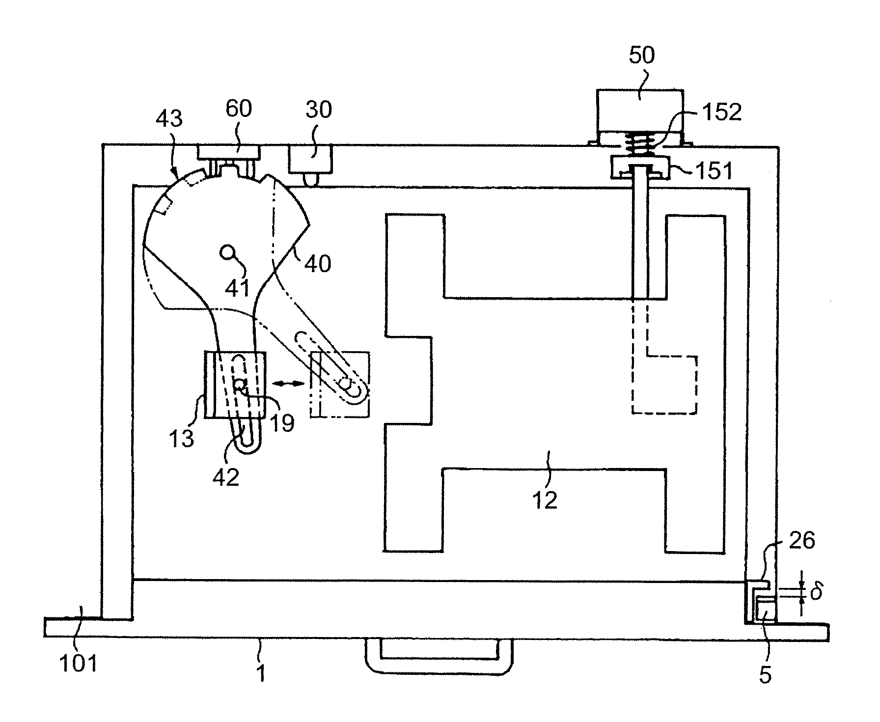
[0061]FIG. 8 is a plan view of the elements forming a cassette attachment unit according to the second embodiment for locking the cassette. The second embodiment differs from the first embodiment in that there is no biasing device (the solenoid 31 and the compression spring 32 shown in FIG. 5) provided to bias the cassette 1. Instead, the second embodiment has a coupling member 151 and a spring 152 that biases the coupling member 151 functioning as the cassette base plate hoisting mechanism. The first embodiment and the second embodiment are identical in other respects. The following description only explains the features that are unique to the second embodiment. The features that are common to the present and first embodiments will be omitted from the description.
[0062]The cassette 1 in the present embodi...
third embodiment
[0079]In the third embodiment, the detecting unit 43 of the link member 40 has two notches and the paper-size detecting unit 60 has three push switches. The number of notches in the detecting unit 43 and the number of push switches of the paper-size detecting unit 60 can be increased or decreased as required. The radius of the detecting unit 43 of the link member 40 can also be set as required.
[0080]Though the present invention has been explained with reference to the a paper feeding cassette, the invention can be equally applied to any functional unit that is detachably attachable to the apparatus body such as developing unit, fixing unit, toner containing unit such as toner bottle and toner cartridge, process cartridge that includes at least image holding member, belt unit including intermediate transfer belt and transfer sheet conveying belt, writing unit that scans a photosensitive member, and double-face unit that reverses the recording sheet. By applying the present invention,...
first embodiment
[0083]In the embodiments of the present invention, the biasing unit of the biasing device acts (switching from off to on) after the cassette is inserted. Alternatively, the biasing unit can be configured to exert a weak bias force (not enough to move the paper feeding cassette) at the time of insertion of the cassette and later exert greater bias force (enough to move the cassette). For example, in the first embodiment, the compression spring 32 can be configured to exert a bias force much weaker than that required to move the cassette 1. When the cassette 1 is inserted into the apparatus body 101, and the interior end of the cassette 1 comes in contact with the compression spring 32, as shown in FIG. 6, the bias force of the compression spring 32 alone can be made to act on the cassette 1 before the solenoid 31 is switched on. This bias force alone is not enough to move the cassette 1. Once the solenoid 31 is switched on, the arm 31a extends, and the compression of the compression ...
PUM
| Property | Measurement | Unit |
|---|---|---|
| Force | aaaaa | aaaaa |
| Size | aaaaa | aaaaa |
Abstract
Description
Claims
Application Information