
Terminal structure of electrical connector

a technology of terminal structure and electrical connector, which is applied in the direction of securing/insulating coupling contact members, coupling device connections, electrical apparatus, etc., can solve the problems of inability to precisely control the size and relatively increased pressing costs, and achieves convenient manufacturing, less space, and better contact elasticity

Inactive Publication Date: 2008-05-22
TSAI CHOU HSUAN
View PDF0 Cites 5 Cited by
  • Summary
  • Abstract
  • Description
  • Claims
  • Application Information

AI Technical Summary

Benefits of technology

"The invention provides a terminal structure of an electrical connector that has an elastic arm that is bent upwards from a bottom end of a fixing portion and extends towards one side of a first surface of the fixing portion. This structure has better contact elasticity, is easy to manufacture, and takes up less space in the terminal slot when assembled. The elastic arm is connected to the bottom end of the fixing portion, and has a curved shape with a narrower top end that exceeds the top end of the fixing portion. This structure provides better contact elasticity, is easy to manufacture, and takes up less space in the terminal slot when assembled."

Problems solved by technology

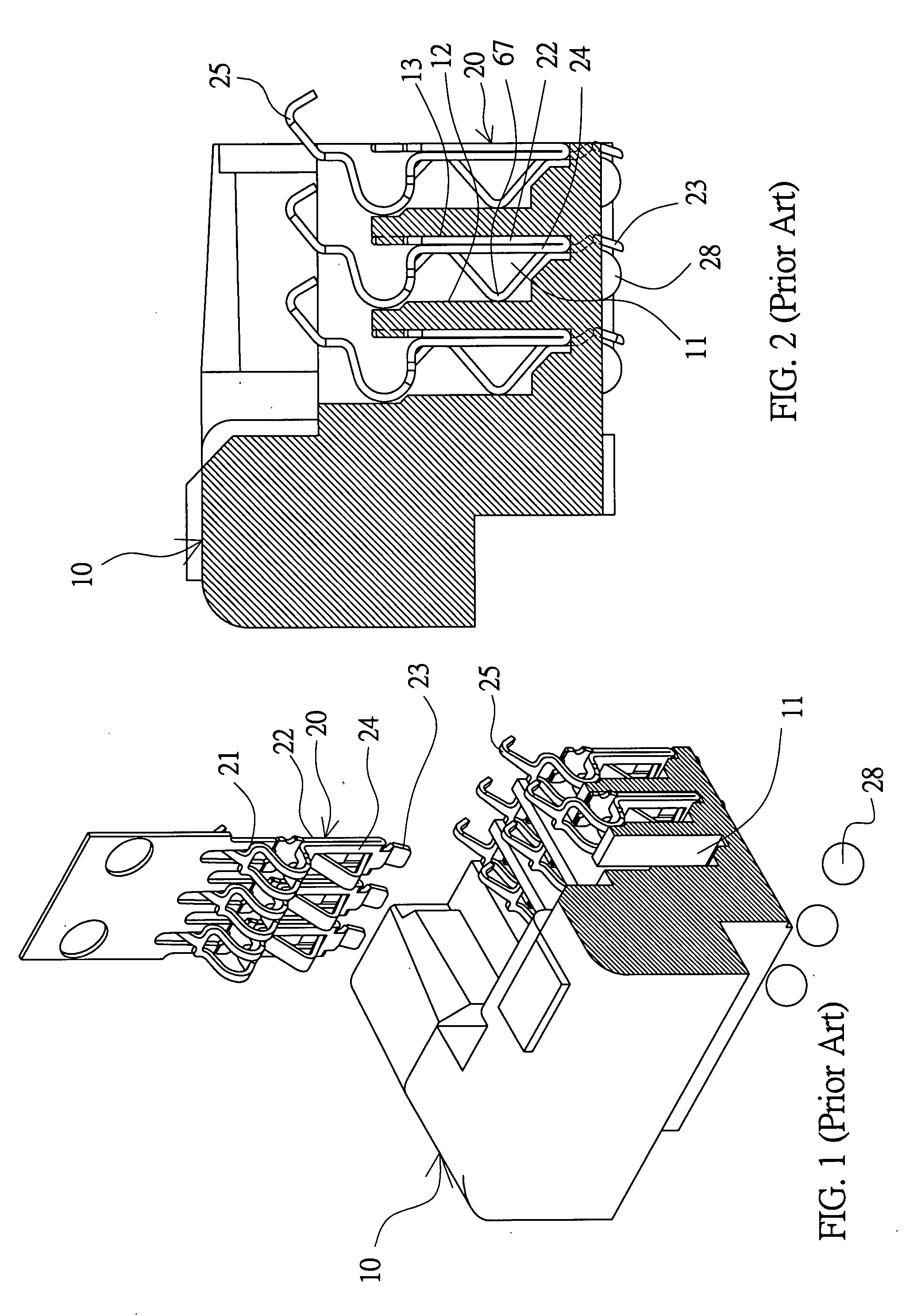
Second, the size cannot be precisely controlled when the first surface of the elastic arm 21 is being pressed and bent, and the pressing cost is relatively increased.

Method used


Image

  • Terminal structure of electrical connector
  • Terminal structure of electrical connector
  • Terminal structure of electrical connector

Examples


Embodiment Construction

[0030]The present invention will be apparent from the following detailed description, which proceeds with reference to the accompanying drawings, wherein the same references relate to the same elements.

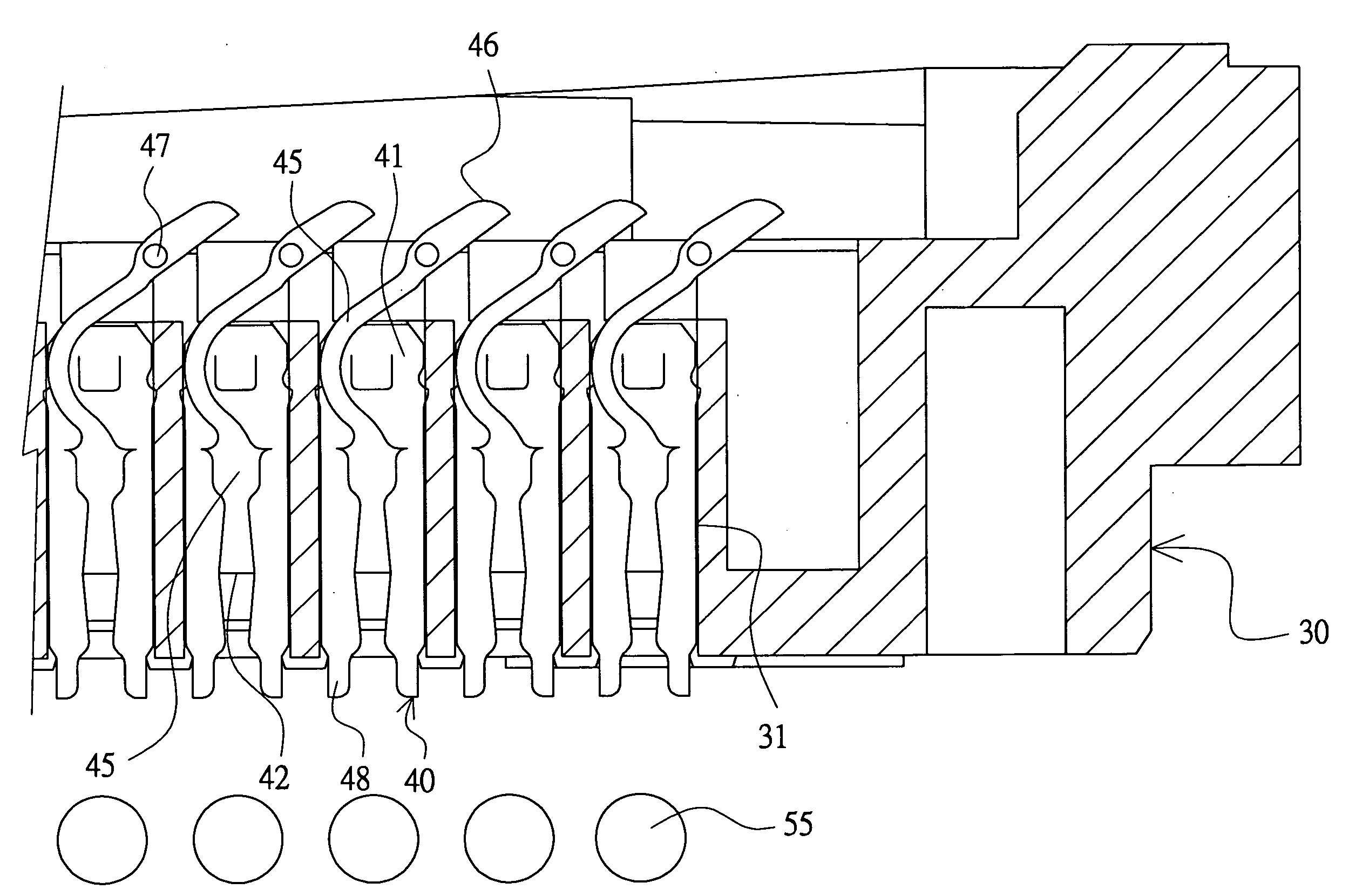
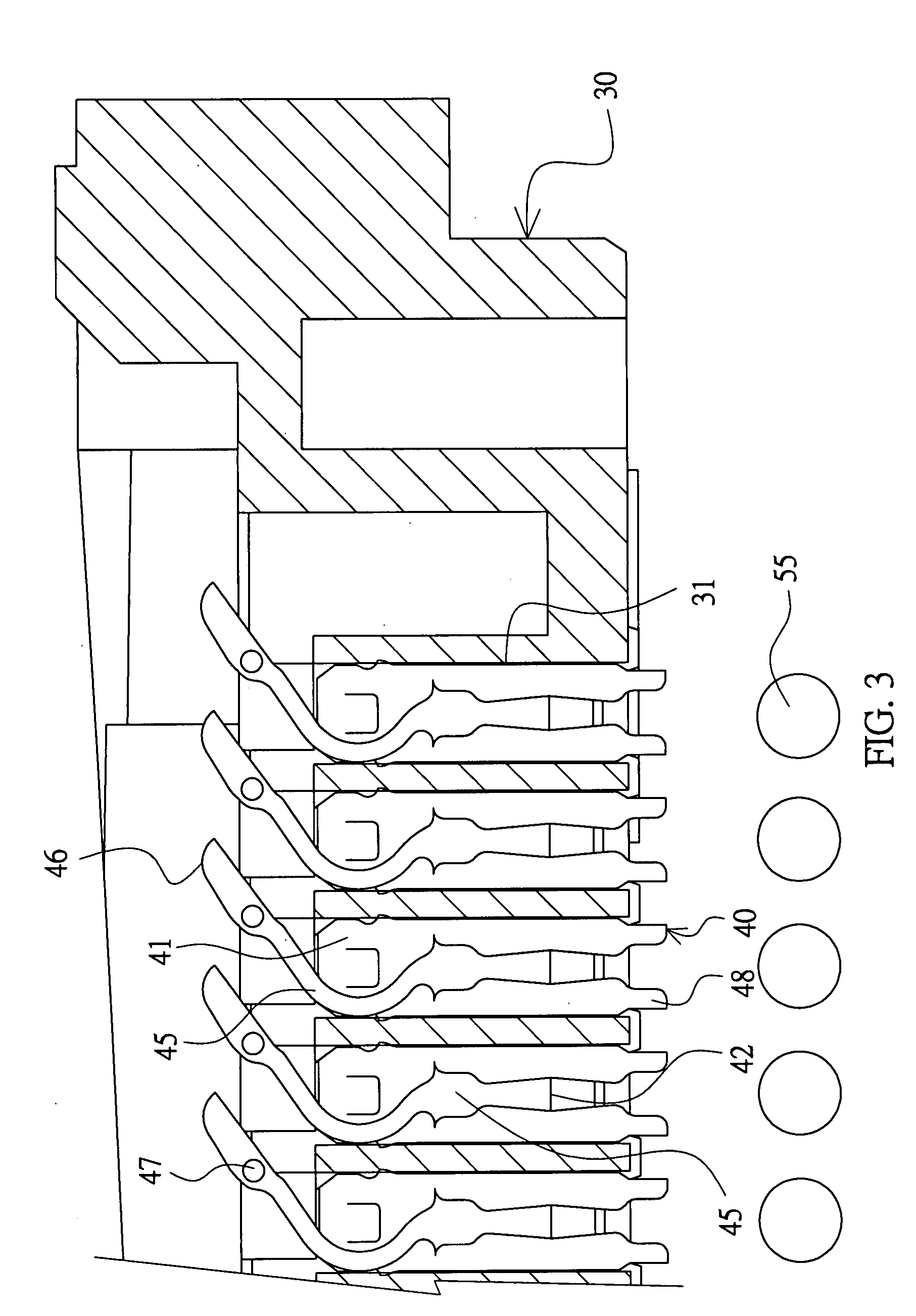
[0031]Referring to FIGS. 3 and 4, an electrical connector according to this embodiment includes a plastic base 30 and a plurality of terminals 40.

[0032]The plastic base 30 is formed with several rows of terminal slots 31.

[0033]As shown in FIG. 5, the terminals 40 are integrally formed by pressing a metal plate 50 so that the continuous terminals 40 formed are connected to a material tape 53. The metal plate 50 has a first surface 51, which extends in a lengthwise direction and a widthwise direction, and a second surface 52, which extends in a thickwise direction and the lengthwise direction and is connected to the first surface 51. The continuous terminals 40 are assembled, from top to bottom, into the terminal slots 31. The terminal 40 includes a fixing portion 41, an elastic arm 45 ...


PUM


Abstract

A terminal structure to be assembled in a terminal slot is integrally formed by pressing a metal plate having first and second surfaces. The terminal structure includes a fixing portion and an elastic arm. The first surface of the fixing portion is fixed in the slot and is wider. The arm is connected to the fixing portion. Over 70% of the first surface of the arm are disposed on the same plane and the first surface of the arm has a curved shape. The first surface of the arm is narrower than the first surface of the fixing portion. An angle smaller than 30 degrees is formed between the first surfaces of the arm and the fixing portion. A top end of the arm exceeds a top end of the fixing portion, and is formed with a movable contact.

Description

BACKGROUND OF THE INVENTION[0001]1. Field of Invention[0002]The invention relates to an electrical connector, and more particularly to a terminal structure of an electrical connector, which may be moved vertically for contact.[0003]2. Related Art[0004]A chip (e.g., a CPU) has a bottom surface formed with several contacts. An electrical connector connected to the chip applies a downward force to fix the chip onto a base so that the contacts of the chip can elastically contact terminals arranged in terminal slots of the base to ensure the electrical connections therebetween.[0005]Referring to FIGS. 1 and 2, an electrical connector to be connected to a chip includes a base 10 and terminals 20. Terminal slots11 are formed on the base 10. The terminals 20 are respectively in the terminal slots 11. Each terminal 20 has a vertically movable elastic arm 21, a fixing portion 22 and a connection sheet 23. The fixing portion 22 tightly presses against the terminal slot 11, and the bottom end t...

Claims


Application Information

Patent Timeline
Patent Type & Authority Applications(United States)
IPC IPC(8): H01R13/40
CPCH01R12/57H01R12/716H01R12/714H01R12/52
Inventor TSAI, CHOU HSUAN
Owner TSAI CHOU HSUAN
Learn More