Connector

a technology of connecting rods and retainers, applied in the direction of coupling device connection, incorrect coupling prevention, securing/insulating coupling contact members, etc., can solve the problems of insufficient strength of partition walls and weakened partition walls, and achieve the effect of stabilizing the mounting position of retainers

Inactive Publication Date: 2008-05-22
SUMITOMO WIRING SYST LTD
View PDF6 Cites 10 Cited by
  • Summary
  • Abstract
  • Description
  • Claims
  • Application Information

AI Technical Summary

Benefits of technology

[0010]The partition walls that partition adjacent cavities include the extended walls that project into the mount hole. Thus, even if external matter, such as a threadlike iron piece, enters the mount hole, a short circuit of the terminal fittings on opposite sides of the partition wall is prevented by a creepage distance made longer by a cranked shape extending along the extended wall. Further, a necessary strength for the partition walls is ensured even if the extended walls are provided, the breakage of the partition walls can be avoided and a function of preventing the short circuit between the terminal fittings can be guaranteed. Furthermore, the extended walls engage the recesses of the retainer with the retainer inserted to the substantially proper depth in the mount hole. Thus, the mounting posture of the retainer can be stabilized.
[0012]The extended walls engage the recesses of the retainer when the retainer is inserted to the proper depth in the mount hole. Thus, the mounting posture of the retainer can be stabilized.
[0013]The retainer preferably is positioned in the housing for movement between a first position where the locking sections are retracted from the cavities to permit the insertion and withdrawal of the terminal fittings into and from the cavities and a second position where the retainer is inserted to the proper depth in the mount hole to insert the locking sections into the cavities, thereby causing the locking sections to act on the substantially properly inserted terminal fittings.

Problems solved by technology

However, the partition wall is weakened by the fitting recess and the strength of the partition wall might be insufficient when the retainer is not mounted.

Method used


Image

  • Connector
  • Connector
  • Connector

Examples


Embodiment Construction

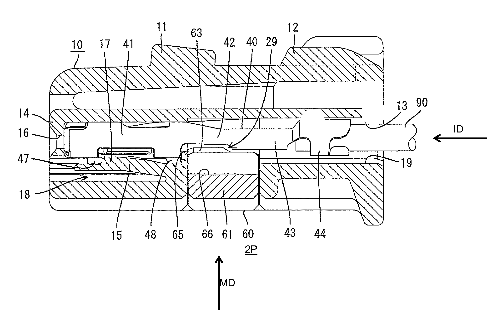
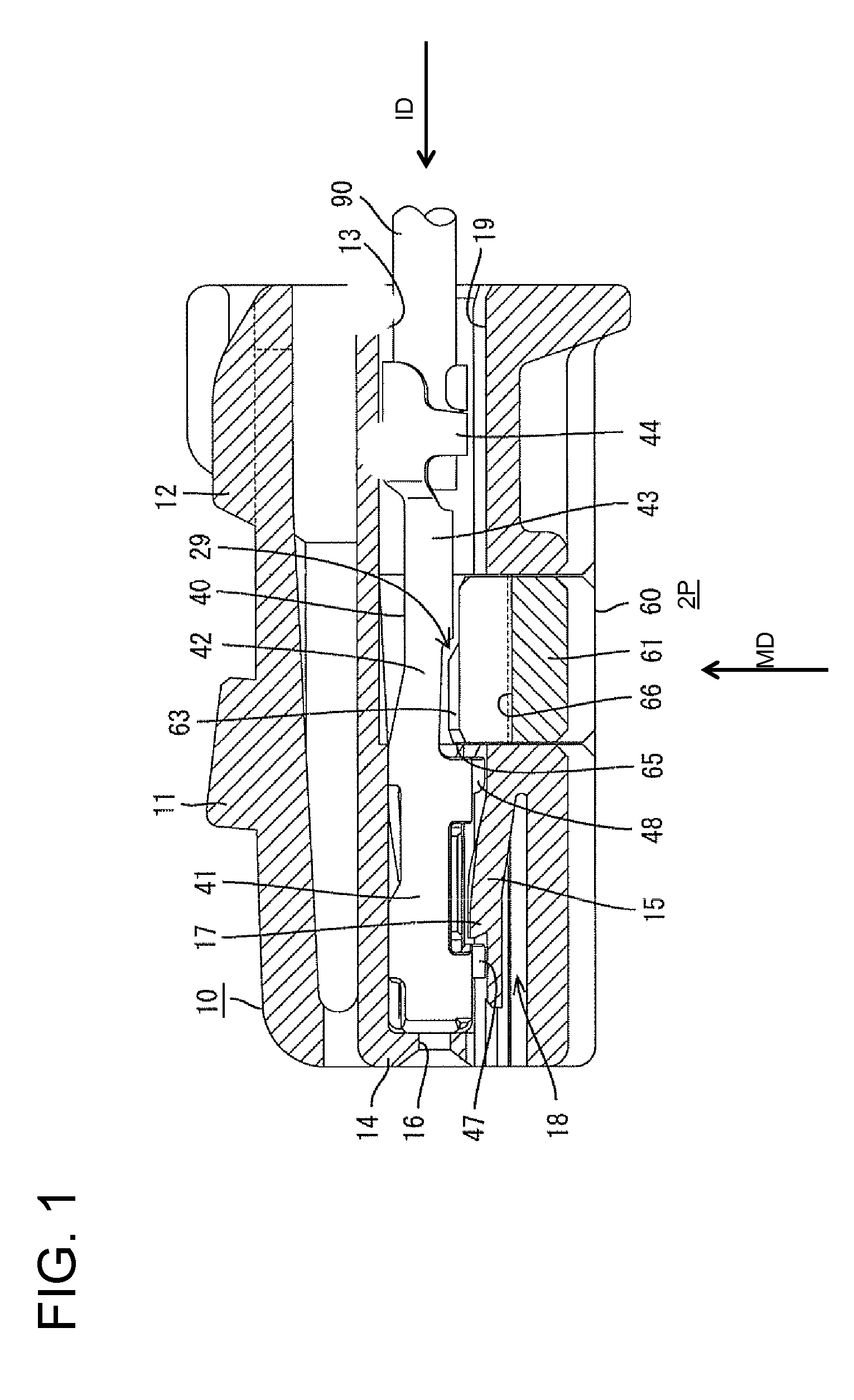
[0027]A connector in accordance with the invention is illustrated in FIGS. 1 to 6 and has a housing 10, terminal fittings 40 and a retainer 60. The housing 10 is connectable with an unillustrated mating housing. A connecting end with the mating connector is referred to as the front.

[0028]The housing 10 is made e.g. of a synthetic resin and is substantially in the form of a flat block. A lock arm 11 is cantilevered backward from the front end of the upper surface of the housing 10. The rear end of the lock arm 11 is resiliently deformable up and down towards and away from the housing 10 with the front end of the lock arm 11 as a support. The lock arm 11 can be engaged with the mating connector housing to hold the two housings together. An operable portion 12 is provided near the rear end of the lock arm 11 and can be pressed to cancel the locked state of the housing 10 with the mating housing.

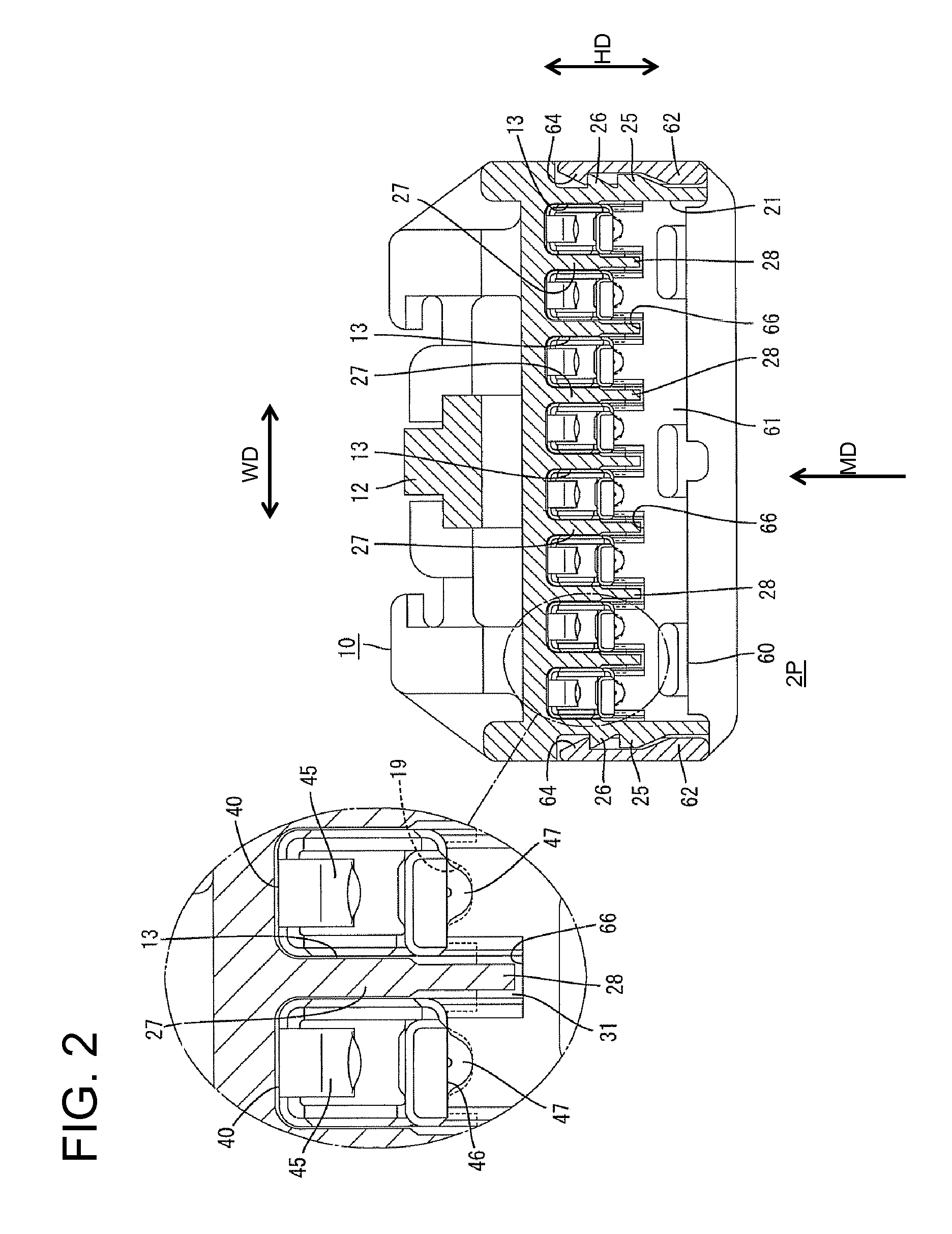
[0029]Cavities 13 are arranged in the width direction WD in the housing 10, and the terminal...


PUM


Abstract

A connector housing (10) is formed with a mount hole (21) for a retainer (60), and the retainer (60) is inserted into the mount hole (21) to lock and retain terminal fittings (40) inserted into cavities (13). Partition walls (28) partitioning the cavities (13) adjacent in width direction in the connector housing (10) are provided with extended walls (28) projecting into the mount hole (21). The retainer (60) is provided with recesses (66) at positions corresponding to the extended walls (28). A creepage distance between the terminal fittings (40) adjacent with the partition wall (27) therebetween is made longer by the extended wall (28), whereby the short circuit of the adjacent terminal fittings (40) can be prevented.

Description

BACKGROUND OF THE INVENTION[0001]1. Field of the Invention[0002]The invention relates to a connector.[0003]2. Description of the Related Art[0004]Japanese Unexamined Patent Publication No. 2003-151672 discloses a connector with a housing formed with cavities arranged side by side across a width direction of the housing. The cavities are configured to receive terminal fittings. A mount hole is formed in an outer surface of the housing and communicates with the respective cavities. The connector also includes a retainer that is insertable into the mount hole to lock and retain the properly inserted terminal fittings.[0005]A partition wall is provided between the cavities that are adjacent in the width direction. The partition wall is cut from the bottom towards the top to form a fitting recess at a position corresponding to the mount hole. The mount hole makes openings in inner walls of the cavities, and the bottom end of the partition wall is at the same height position as these open...

Claims


Application Information

Patent Timeline
Patent Type & Authority Applications(United States)
IPC IPC(8): H01R13/40
CPCH01R13/4362H01R13/64
Inventor NISHIDE, SATORU
Owner SUMITOMO WIRING SYST LTD
Why Eureka
Try Eureka