Cleaner

a technology of cleaning blades and blades, which is applied in the direction of vacuum cleaners, cleaning equipment, domestic applications, etc., can solve the problems of a considerable load in moving the cleaner, and achieve the effects of reducing the traveling load, increasing the cleaning efficiency, and low friction

Inactive Publication Date: 2008-05-29
SAMSUNG GWANGJU ELECTRONICS CO LTD
View PDF6 Cites 10 Cited by
  • Summary
  • Abstract
  • Description
  • Claims
  • Application Information

AI Technical Summary

Benefits of technology

[0010]An aspect of the present disclosure is to solve at least the above problems and / or disadvantages and to provide at least the advantages described below. Accordingly, an aspect of the present disclosure is to provide a cleaner capable of selectively jutting out a blade toward a surface to be cleaned, thereby increasing a cleaning efficiency, when the surface to be cleaned has a low friction force, and rotating the blade in a body direction, thereby reducing a traveling load to the cleaner, when the surface to be cleaned has a high friction force.

Problems solved by technology

However, in this case, if the surface to be cleaned has a high friction force, as in a carpet or the like, a problem occurs, in that the projected blade produces friction with the surface to be cleaned and, thus, acts as a considerable load in moving the cleaner.

Method used


Image

  • Cleaner
  • Cleaner
  • Cleaner

Examples


Embodiment Construction

[0036]Hereinafter, a cleaner according to exemplary embodiments of the present disclosure will be described in detail with reference to the accompanying drawing figures.

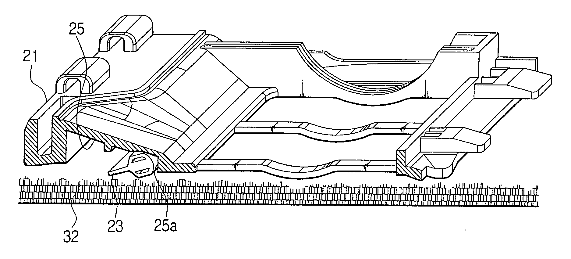
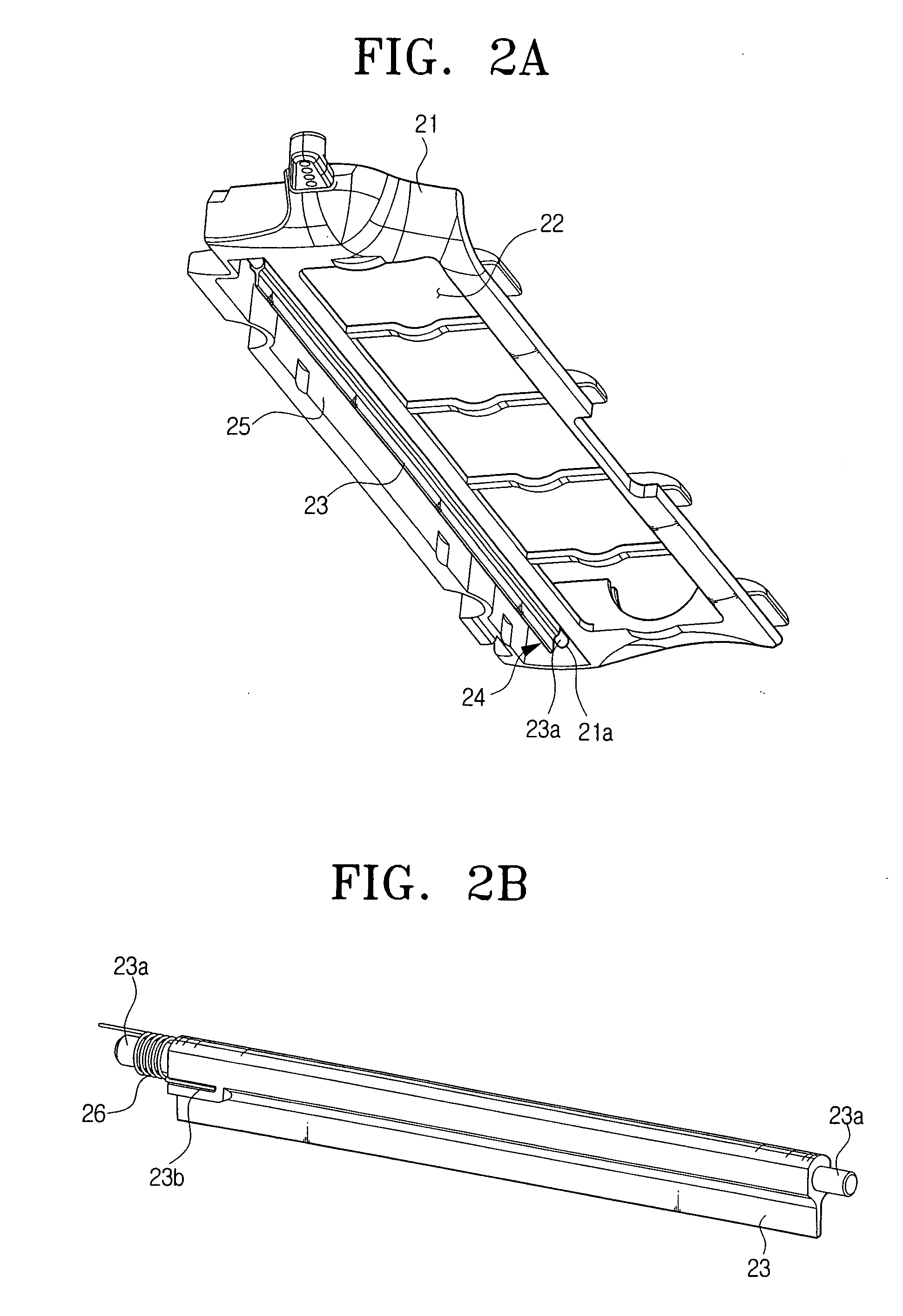
[0037]FIG. 2A is a perspective view exemplifying a portion to which a blade is mounted to an undersurface of a cleaner according to an exemplary embodiment of the present disclosure; and FIG. 2B is a perspective view magnifiedly exemplifying only the blade of FIG. 2A. Referring to FIG. 2A, the cleaner according to the exemplary embodiment of the present disclosure includes a blade 23, a rotating unit 24, and an accommodating space 25. The blade 23 is attached in the vicinity of an inlet 22 for drawing in dust or dirt from a surface to be cleaned at a lower end of a body 21 of the cleaner. The rotating unit 24 rotates the blade 23. The accommodating space 25 is formed in the body, so that the blade 23 is received therein.

[0038]The rotating unit 24 is provided with a rotating axis 23a, a coupling hole 21a, and a spiral...


PUM


Abstract

A vacuum cleaner having a blade, which rotates, is disclosed. The vacuum cleaner includes a body, a blade attached to a lower end of the body, and a rotating unit attached to the body so as to rotate the blade.

Description

CROSS-REFERENCE TO RELATED APPLICATIONS[0001]This application claims the benefit under 35 U.S.C. § 119(a) of Korean Patent Application Nos. 10-2006-0118340 and 10-2006-0119837, filed Nov. 28, 2006 and Nov. 30, 2006, respectively, in the Korean Intellectual Property Office, the entire disclosure of both of which is incorporated herein by reference.BACKGROUND OF THE INVENTION[0002]1. Field of the Invention[0003]The present disclosure relates generally to a vacuum cleaner and, more particularly, to a moveable blade, which is attached to a lower end of the cleaner.[0004]2. Description of the Related Art[0005]In general, a vacuum cleaner at an undersurface thereof has an inlet, which draws in dust or dirt, and a blade, which is projected downward to collect dust or dirt in the vicinity of the inlet, thereby increasing a cleaning efficiency.[0006]FIG. 1 is a perspective view of an undersurface of a general vacuum cleaner, particularly, a robot vacuum cleaner.[0007]As illustrated in FIG. 1...

Claims


Application Information

Patent Timeline
Patent Type & Authority Applications(United States)
IPC IPC(8): A47L5/00
CPCA47L9/0666A47L9/06
Inventor KIM, MYEONG-HOJEUNG, SAM-JONGSONG, JEONG-GONLEE, JU-SANGKO, JANG-YOUNKIM, KYOUNG-WOUNGLEE, HAK-BONG
Owner SAMSUNG GWANGJU ELECTRONICS CO LTD
Why Eureka
Try Eureka