Touch Sensing Using Shadow and Reflective Modes

a technology of applied in the field of touch sensing using shadow and reflection mode, can solve the problem that the touch screen cannot detect touch events

Inactive Publication Date: 2008-05-29
MICROSOFT TECH LICENSING LLC
View PDF18 Cites 634 Cited by
  • Summary
  • Abstract
  • Description
  • Claims
  • Application Information

AI Technical Summary

Problems solved by technology

This mode of operation is affected by the level of ambient visible lighting and if it is too dark there may be no shadow and so the touch screen will fail to detect touch events.

Method used


Image

  • Touch Sensing Using Shadow and Reflective Modes
  • Touch Sensing Using Shadow and Reflective Modes
  • Touch Sensing Using Shadow and Reflective Modes

Examples


Embodiment Construction

[0026]The detailed description provided below in connection with the appended drawings is intended as a description of the present examples and is not intended to represent the only forms in which the present example may be constructed or utilized. The description sets forth the functions of the example and the sequence of steps for constructing and operating the example. However, the same or equivalent functions and sequences may be accomplished by different examples.

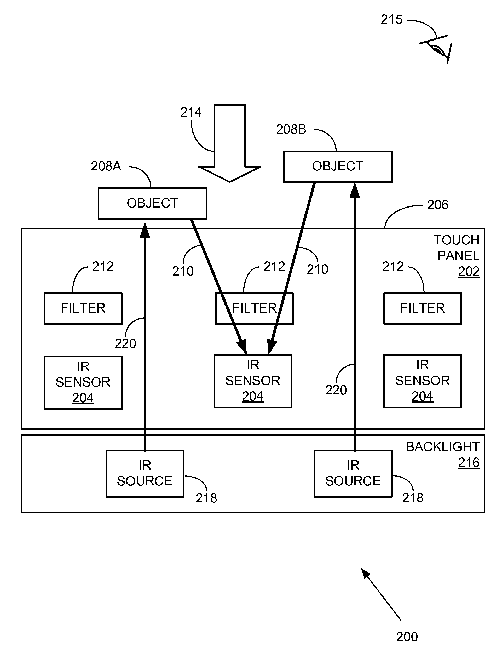
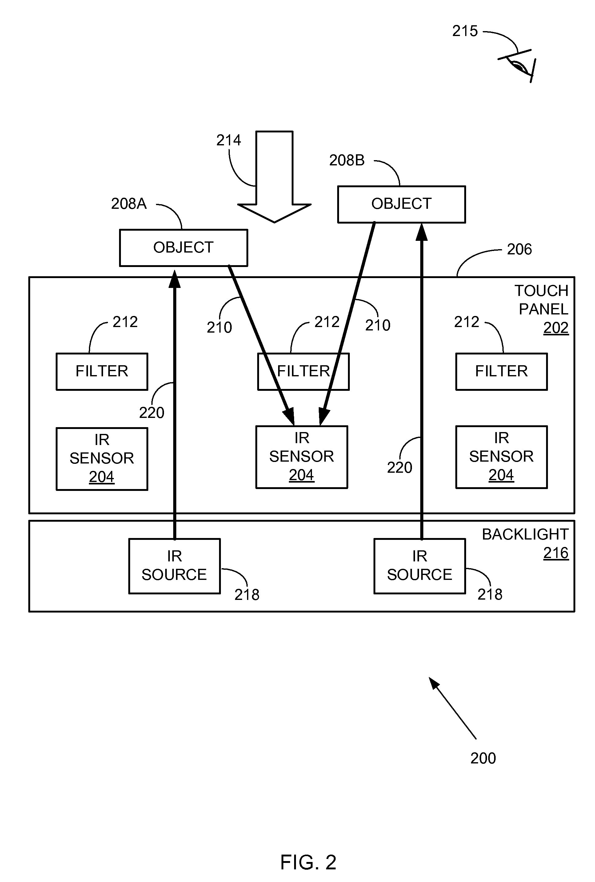
[0027]Use of infra-red sources as opposed to visible light, as described in U.S. utility application Ser. No. 11 / 604,491 entitled “Infrared sensor integrated in a touch panel” filed on Nov. 27, 2006, which is incorporated herein by reference, has the benefit that the graphic image displayed on the touch screen is not affected by the detection of touch events. Additionally, the amount of ambient visible light does not affect the detection.

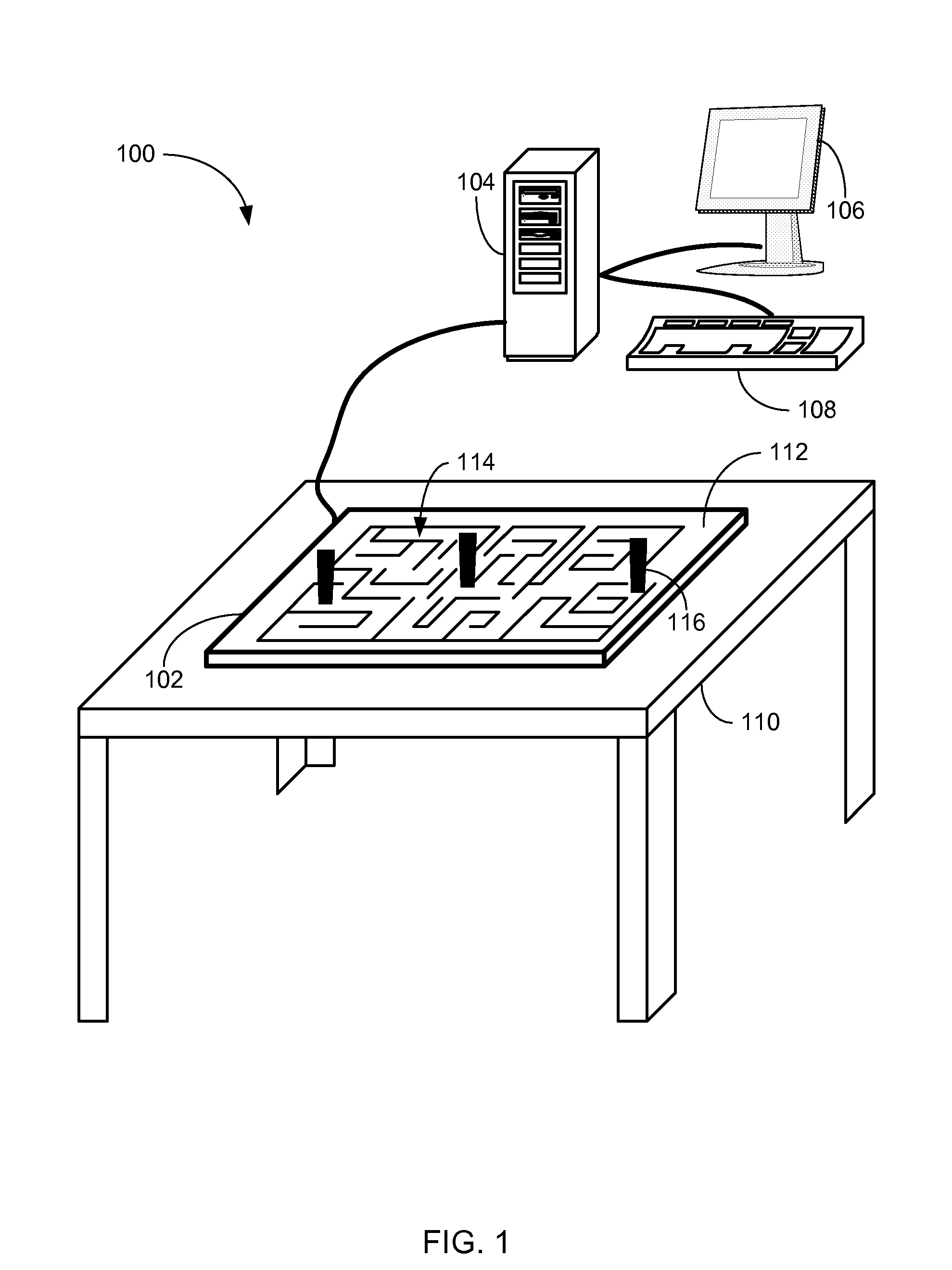
[0028]FIG. 1 illustrates an exemplary interactive display system incorporating a t...


PUM


Abstract

A touch panel is described which uses at least one infrared source and an array of infrared sensors to detect objects which are in contact with, or close to, the touchable surface of the panel. The panel may be operated in both reflective and shadow modes, in arbirary per-pixel combinations which change over time. For example, if the level of ambient infrared is detected and if that level exceeds a threshold, shadow mode is used for detection of touch events over some or all of the display. If the threshold is not exceeded, reflective mode is used to detect touch events. The touch panel includes an infrared source and an array of infrared sensors.

Description

CROSS-REFERENCE TO RELATED APPLICATION(S)[0001]This application is a continuation in part of U.S. utility application Ser. No. 11 / 604,491 entitled “Infrared sensor integrated in a touch panel” filed on Nov. 27, 2006, which is incorporated herein by reference.BACKGROUND[0002]Touch screens (or touch panels) are increasingly being used to provide user interfaces for devices such as tablet PCs, self-service terminals and mobile devices such as PDAs and mobile telephones. There are a number of different technologies which may be used, for example a resistive touch panel in which touching the screen causes layers, which are normally separated by a small gap, to come into contact or a capacitive touch panel in which contact with a conductive object changes the capacitance.[0003]In another example, a touch screen may use optical sensors (e.g. an optical sensor array) to detect when a screen is touched. Use of optical sensors enables multi-touch sensing, i.e. detection of multiple simultaneo...

Claims


Application Information

Patent Timeline
Patent Type & Authority Applications(United States)
IPC IPC(8): G06F3/042
CPCG06F2203/04109G06F3/0421
Inventor IZADI, SHAHRAMHODGES, STEPHENBUTLER, DAVID ALEXANDERRRUSTEMI, ALBAN
Owner MICROSOFT TECH LICENSING LLC
Why Eureka
Try Eureka