Method and system for automatically determining the camera field of view in a camera network

a camera network and camera field technology, applied in the field of methods, can solve the problems of inability to automatically determine the camera field of view in the camera network, inability to maintain such information in large camera systems, and inability to accurately determine the field of view of the camera,

Active Publication Date: 2008-05-29
HONEYWELL INT INC
View PDF49 Cites 27 Cited by
  • Summary
  • Abstract
  • Description
  • Claims
  • Application Information

AI Technical Summary

Benefits of technology

[0018]According to yet another aspect, a method for automatically determining a camera field of view in a camera network comprises measuring respective angle directions of the fields of views of a plurality of spatially separated cameras relative to magnetic north; generating direction measurement signals corresponding to the measured angle directions; measuring respective elevation angles of the spatially separated cameras; and generating elevation measurement signals corresponding to the measured elevation angles. Advantageously, measuring the cameras' direction and elevation angles enables the fields of view of the cameras to be determined automatically without having to determine the camera initial mounting positions during camera installation.

Problems solved by technology

Although requiring the camera installer to note the camera direction and angle could be entered into a database and used to automatically point a camera to an event of interest, maintaining such information in large camera systems is difficult and expensive requiring additional labor.
Furthermore, cameras are frequently moved or added incrementally causing the information to be incorrect or non-existent.
This lack of spatial reference with respect to the rest of the facility or compound and increases the work load for the security staff.

Method used


Image

  • Method and system for automatically determining the camera field of view in a camera network
  • Method and system for automatically determining the camera field of view in a camera network
  • Method and system for automatically determining the camera field of view in a camera network

Examples


Embodiment Construction

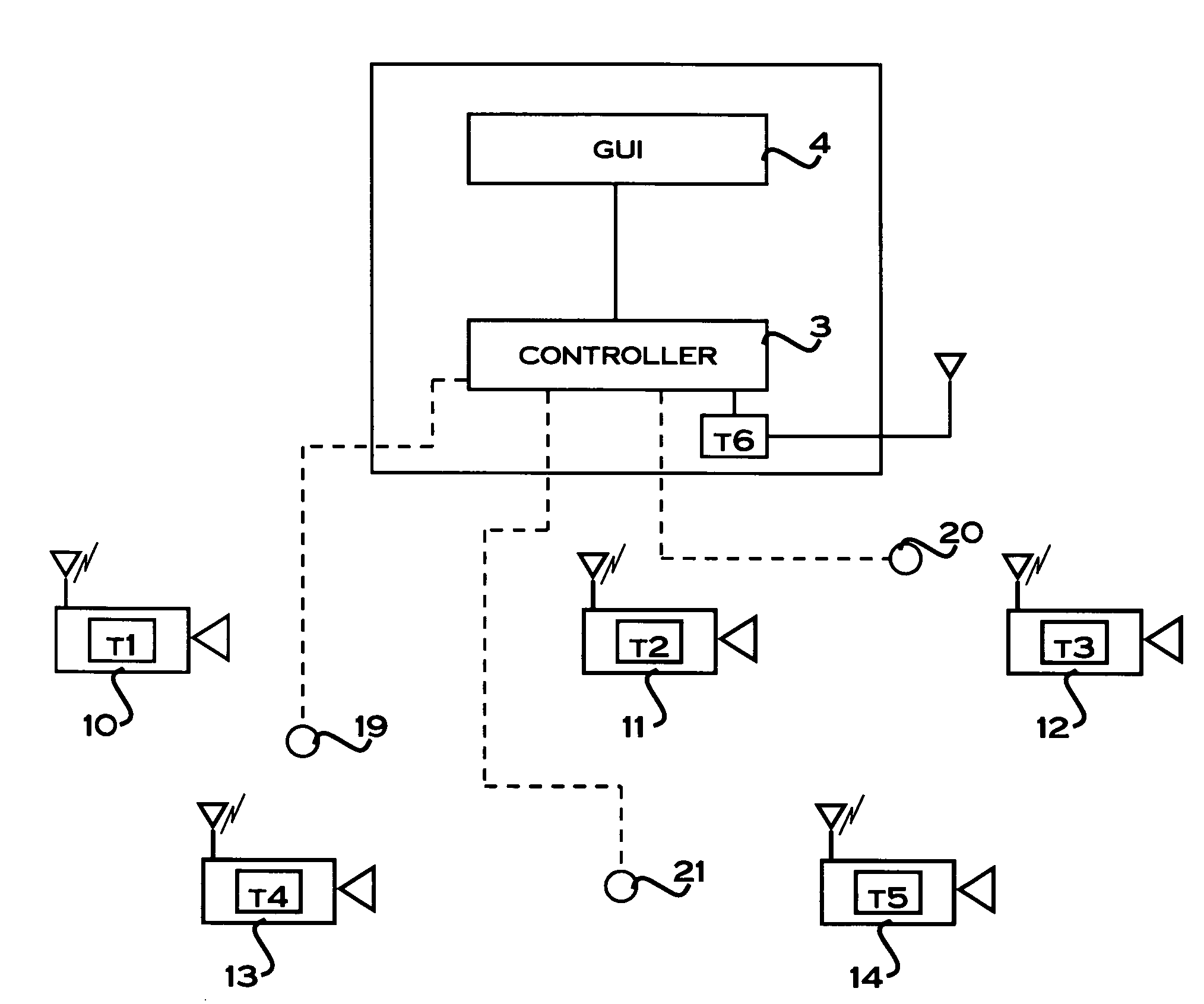
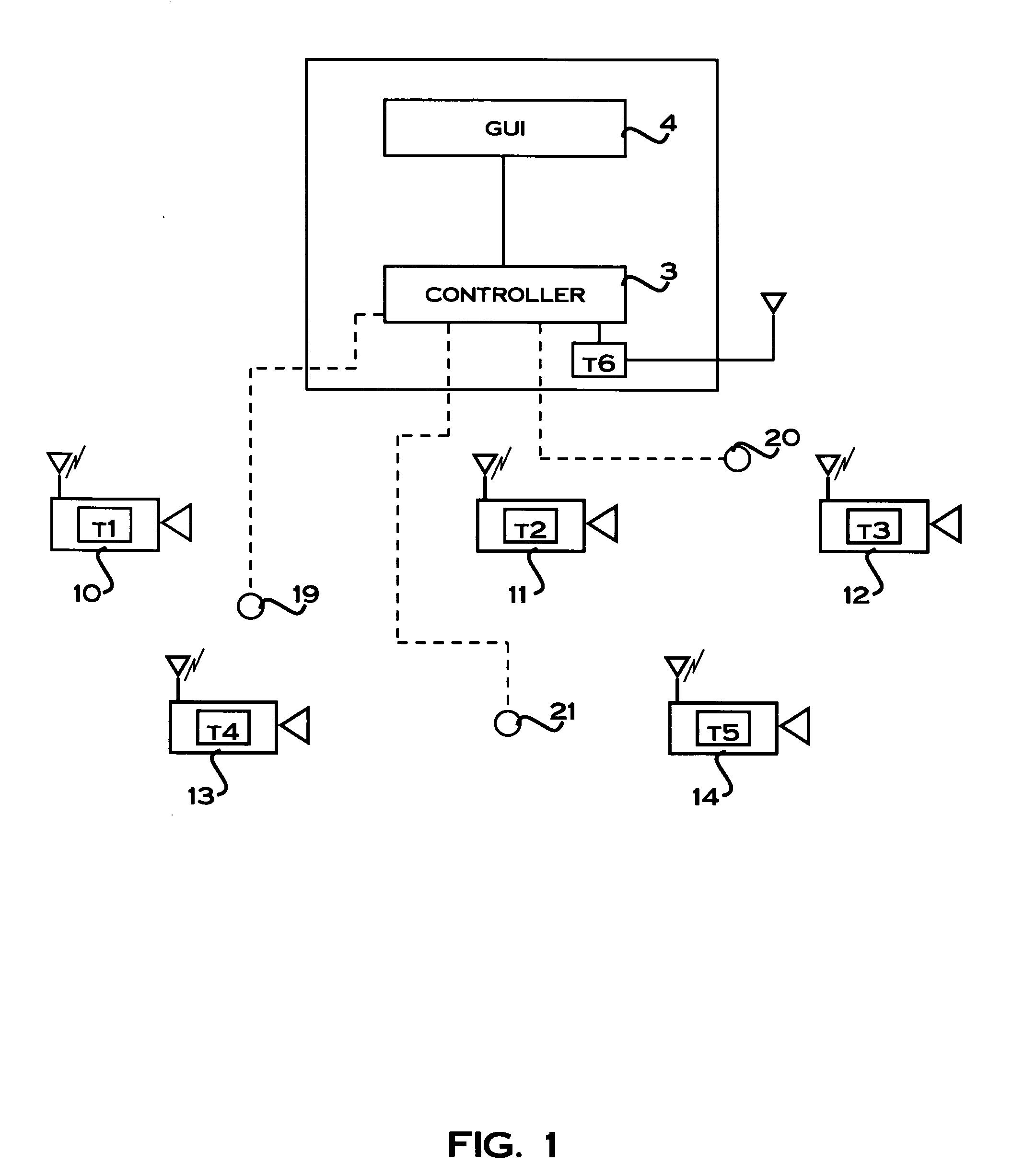
[0031]The system and method for automatically determining the camera field of view in a camera network of the illustrative embodiments provides an approach to enable cameras to automatically determine their field of view without requiring installers or other users to obtain and input additional field of view information into the camera network. Furthermore, the approach enables the camera network to automatically select one or more cameras with a field of field containing an event of interest in proximity to the one or more cameras. Using this approach, events of interest outside the fields of views of particular cameras can be captured automatically by rotating the particular cameras to bring the event of interest into their fields of views.

[0032]In order to explain the system and method for automatically configuring the camera field of view in a camera network according to the illustrative embodiment, reference will first be made to a camera network in which the system and method ...


PUM


Abstract

A system and method for automatically determining the camera field of view in a camera network. The system has a plurality of spatially separated cameras and direction sensors, carried on respective cameras, configured to measure the angle directions of the field of views of the cameras. Elevation sensors are operably coupled to respective cameras to measure the elevation angles of thereof. A controller is configured to process direction and elevation measurement signals transmitted from the cameras to automatically determine the cameras' fields of views. One or more cameras having a field of view containing or nearby an event of interest can be selected from the determined field of views and indicated to a user via a graphical user interface. Selected cameras which are rotatably mounted can be rotated if need be to automatically bring the event of interest into the field of views of the selected cameras.

Description

TECHNICAL FIELD[0001]Embodiments relate to methods and systems for configuring device networks and, more particularly, to systems and methods for automatically determining the camera field of view in a camera network, such as a video based camera network. Also, embodiments relate to techniques for configuring cameras with a field of view that contains the event of interest.BACKGROUND[0002]Advances in digital video camera technology have resulted in high quality cameras with lower cost and greater image resolution. This has permitted facility owners to deploy an increasing number of cameras that must be monitored by a fixed size security staff. Critical to making the existing staff as productive as possible is to provide additional information on which cameras have the most important information. When an event of interest occurs within a facility or compound, providing a mechanism to select the cameras with a field of view that contains the event of interest is a significant capabili...

Claims


Application Information

Patent Timeline
Patent Type & Authority Applications(United States)
IPC IPC(8): H04N5/225
CPCG08B13/1963H04N7/181G08B13/19689G08B13/19636
Inventor HUSETH, STEVE D.BEDROS, SAAD J.
Owner HONEYWELL INT INC
Why Eureka
Try Eureka