Transflective liquid crystal display panel, liquid crystal display module and liquid crystal display thereof

a liquid crystal display panel and liquid crystal display module technology, applied in static indicating devices, instruments, non-linear optics, etc., can solve the problems of inability to achieve the desired displaying effect of one pixel, the inability of the transmissive region and the reflective region in one pixel to simultaneously display the four same gray levels, and the inability to achieve the effect of enhancing the image displaying quality

Inactive Publication Date: 2008-05-29
INNOLUX CORP
View PDF8 Cites 34 Cited by
  • Summary
  • Abstract
  • Description
  • Claims
  • Application Information

AI Technical Summary

Benefits of technology

[0011]The invention is directed to a transflective LCD having a transmissive pixel and a reflective pixel respectively driven by a transmissive pixel voltage and a reflective pixel voltage. Independently controlling the transmissive pixel and the reflective pixel allows the brightness or the gray level displayed by the transmissive pixel and the reflective pixel to achieve a desired effect, thereby enhancing the image displaying quality.

Problems solved by technology

Therefore, in the pixel structure of the conventional transflective LCD, it is difficult for one pixel voltage V to make the transmissive region and the reflective region display the same gray level.
Therefore, the transmissive region and the reflective region in one pixel cannot simultaneously reach the desired displaying effect.
However, the same set of pixel voltages are used, so it is impossible to make the transmissive region and the reflective region simultaneously display the four same gray levels.
However, the manufacturing processes are complicated and expensive.
However, the light of the transmissive region only comes from the backlight source, and its brightness and color cannot change with the change of the environmental light.
Therefore, if the transmissive region and the reflective region are driven by the same pixel voltage, the brightness or colors co-presented by the transmissive region and the reflective region often deviate from the optimum settings, which are set when the product is finished and ready to be shipped out, so that the incongruent condition is obtained when the environmental light changes with the changes of the time and the environment.

Method used


Image

  • Transflective liquid crystal display panel, liquid crystal display module and liquid crystal display thereof
  • Transflective liquid crystal display panel, liquid crystal display module and liquid crystal display thereof
  • Transflective liquid crystal display panel, liquid crystal display module and liquid crystal display thereof

Examples


first embodiment

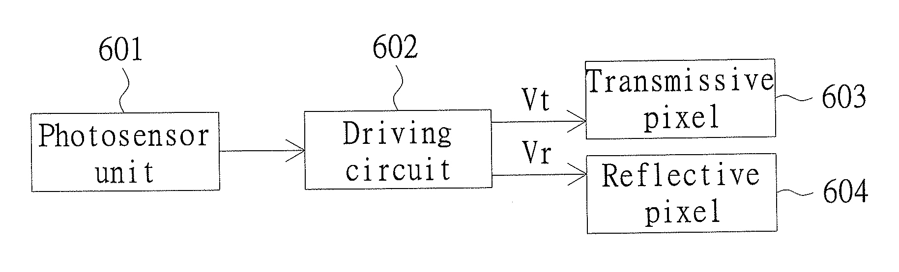
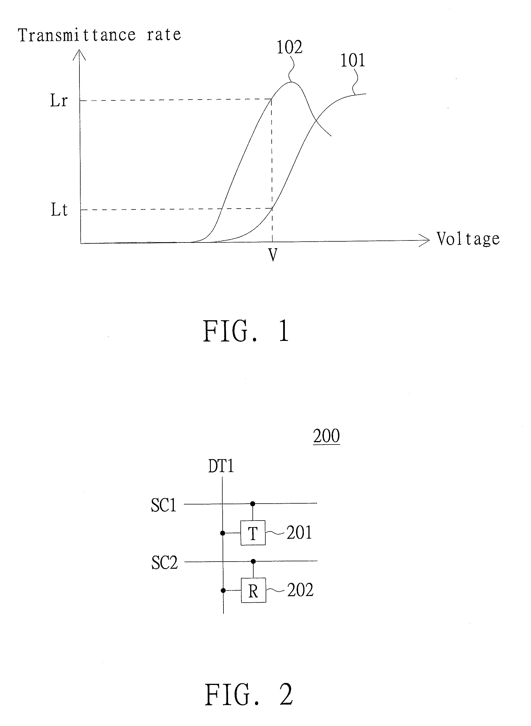
[0034]FIG. 2 is a partial schematic illustrating transflective LCD panel 200 according to a first embodiment of the invention. Transflective LCD panel 200 includes a plurality of scan lines, a plurality of data lines, a plurality of transmissive pixels 201 (represented by “T”), and a plurality of reflective pixels 202 (represented by “R”). Referring to FIG. 2, it shows scan lines SC1 and SC2, a data line DT1, a transmissive pixel 201 and a reflective pixel 202 of the transflective LCD panel 200. The transmissive pixel 201 is controlled by the scan line SC1 and receives the transmissive pixel voltage transmitted from the data line DT1. The backlight emitted from a backlight source passes through the transmissive pixel 201 at a transmittance rate related to the transmissive pixel voltage. The reflective pixel 202 is controlled by the scan line SC2, and receives the reflective pixel voltage transmitted from the data line DT1. The input timings and sequence of the transmissive pixel vol...

second embodiment

[0041]The light for the reflective pixel comes from the environmental light and the light for the transmissive pixel comes from the backlight, so the spectrums of the environmental light and the backlight are usually different, as illustrated in the spectrums of FIG. 5. A spectrum 501 is a backlight spectrum and a spectrum 502 is an environmental light spectrum wherein spectrum 502 changes with a change of the spatiotemporal environment.

[0042]With regard to the transmissive pixel and the reflective pixel needing to simultaneously display the same gray level, the displayed brightness of the transmissive pixel is substantially different from the displayed brightness of the reflective pixel because the light source spectrums of the transmissive pixel and the reflective pixel are different from each other. Consequently, some specific black-and-white brightness or color, which is to be displayed in the frame, is influenced by the environmental light of the reflective pixel and is thus di...

third embodiment

[0047]FIG. 7 illustrates a transflective LCD panel according to a third embodiment of the invention. The LCD panel illustrated in FIG. 7 is distinguished from that of the first embodiment in that the LCD panel of the third embodiment has a number of transmissive pixels T and a number of reflective pixels R, and the resolution of the transmissive pixels is unequal to the resolution of the reflective pixels. The transmissive pixels form a number of transmissive pixel rows including, for example, transmissive pixel rows 701 and 703. The reflective pixels form reflective pixel rows including, for example, reflective pixel row 702.

[0048]The transmissive pixel T receives the transmissive pixel voltage transmitted from the data line. The backlight emitted from a backlight source passes through the transmissive pixel at a transmittance rate related to the transmissive pixel voltage. The reflective pixel R receives the reflective pixel voltage transmitted from the data line. The environmenta...


PUM

PropertyMeasurementUnit
transmittance ratesaaaaaaaaaa
transmittance rateaaaaaaaaaa
frequencyaaaaaaaaaa

Abstract

A transflective LCD panel includes scan lines, data lines, transmissive pixels and reflective pixels. Each transmissive pixel is configured to receive a transmissive pixel voltage transmitted from one of the data lines and displays a first gray level related to the transmissive pixel voltage. Each reflective pixel receives a reflective pixel voltage transmitted from one of the data lines and displays a second gray level related to the reflective pixel voltage. When the transmissive pixel and the reflective pixel are used to display a same gray level, the transmissive pixel voltage and the reflective pixel voltage are predetermined such that corresponding first and second gray levels substantially equal each other.

Description

[0001]This application claims the benefit of Taiwan application Serial No. 95143644, filed Nov. 24, 2006, the subject matter of which is incorporated herein by reference in its entirety.BACKGROUND OF THE INVENTION[0002]1. Field of the Invention[0003]The invention relates in general to a transflective liquid crystal display (LCD), and more particularly to a transflective LCD having a transmissive pixel and a reflective pixel, which are respectively controlled by different pixel voltages.[0004]2. Description of the Related Art[0005]In a conventional transflective liquid crystal display (LCD), such as a vertically-aligned (VA) mode transflective LCD, each pixel has a pixel electrode and a reflective electrode electrically connected to each other. The pixel electrode and the reflective electrode respectively form a transmissive region and a reflective region, and the pixel electrode and the reflective electrode are driven by the same pixel voltage. As for the transmissive region, the pi...

Claims


Application Information

Patent Timeline
Patent Type & Authority Applications(United States)
IPC IPC(8): G02F1/133G02F1/1335
CPCG02F1/133555G09G3/3611G09G2300/0456G09G2360/144G09G2310/0235G09G2320/0626G09G2300/0465
Inventor LIN, CHAO-LIENWU, TING-YILEE, YI-CHIN
Owner INNOLUX CORP
Why Eureka
Try Eureka