Plating method

a technology for electronic appliances and coatings, applied in the direction of superimposed coating process, organic chemistry, coatings, etc., can solve the problems of limited diversification of the external appearance of the terminal, high difficulty in diversified colors of the metal case of the terminal, and high risk of scratching of paints

a technology for electronic appliances and coatings, applied in the direction of superimposed coating process, organic chemistry, coatings, etc., can solve the problems of limited diversification of the external appearance of the terminal, high difficulty in diversified colors of the metal case of the terminal, and high risk of scratching of paints

US20080124468A1Inactive Publication Date: 2008-05-29SAMSUNG ELECTRONICS CO LTD

Image

  • Plating method
  • Plating method
  • Plating method

Examples


Embodiment Construction

[0019]Hereinafter, preferred embodiments of the present invention will be described with reference to the accompanying drawings. In the following description of the present invention, a detailed description of known functions and configurations incorporated herein will be omitted when it may make the subject matter of the present invention rather unclear.

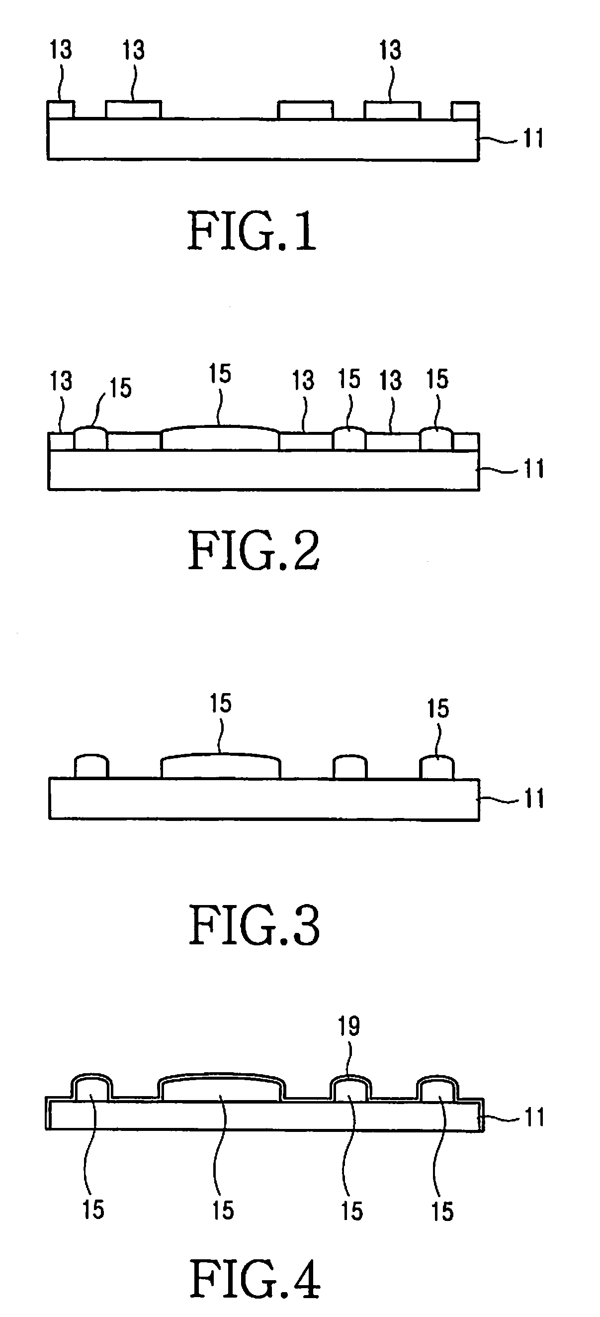
[0020]In a plating method of the invention, a plating pattern is printed on one surface of a plating base, and a plating layer is formed on the remainder of the plating pattern 13 to thereby form a trademark, logo, a three-dimensional pattern, or the like on the plating surface.

[0021]The plating method includes preparing the plating base, printing the plating pattern on a plating surface of the plating base, and plating the plating surface of the plating base, wherein in the plating step, the plating layer is formed on a portion where the plating pattern is not printed.

[0022]Description will now be made to the plating method accordi...


PUM

PropertyMeasurementUnit
weightaaaaaaaaaa
colorsaaaaaaaaaa
sizeaaaaaaaaaa

Abstract

Disclosed is a plating method which, includes preparing a plating base; printing a plating pattern on a plating surface of the plating base; and plating the plating surface of the plating base. During plating, a plating layer is formed on a portion where the plating pattern is not printed. The method is provided for contributing to diversification of the external appearance of a compact type device such as portable terminals, is capable of printing three-dimensional patterns as well as a trademark and a logo, and is capable of highlighting the metallic texture together with three dimensional solid patterns.

Description

PRIORITY[0001]This application claims priority under 35 U.S.C. §119(a) to an application entitled “Plating Method” filed in the Korean Industrial Property Office on Nov. 23, 2006 and assigned Serial No. 2006-0116470, the contents of which are hereby incorporated by reference.BACKGROUND OF THE INVENTION[0002]1. Field of the Invention[0003]The present invention relates to cladding of electronic appliances such as a portable mobile communication terminal, and more particularly to a plating method of a case of a compact type electronic appliance.[0004]2. Description of the Related Art[0005]Generally, when selecting domestic appliances, a user takes functionality, performance, durability, and other criteria into consideration. However, since some appliances such as a refrigerator, an air conditioner, and other similar appliances occupy large space and have simple appearances, it has been recently attempted to makes the external appearance thereof aesthetically pleasing. The domestic appl...

Claims


Application Information

Patent Timeline
29 May 2008
Publication
US20080124468A1
IPC
B05D3/06
CPC
C23C4/18; C25D5/022; C23C28/02; C23C4/01; C23C28/00; B05D3/06
Inventors
KIM, IL-JIN; LEE, YOON-HEE