Glare reduction demonstrator

a demonstrator and glare reduction technology, applied in educational appliances, instruments, educational models, etc., can solve problems such as failure to disclose counter demonstrators, and achieve the effect of easy receipt and exchange of graphi

Inactive Publication Date: 2008-05-29
REIBER PASCAL
View PDF15 Cites 12 Cited by
  • Summary
  • Abstract
  • Description
  • Claims
  • Application Information

AI Technical Summary

Benefits of technology

[0023]A still further objective is to provide such a device that is able to easily receive and exchange graphic images of selected scenes.

Problems solved by technology

However, the prior art fails to disclose a counter demonstrator that adjusts to the height of a customer so as to demonstrate the improved visibility of polarized lenses.

Method used


Image

  • Glare reduction demonstrator
  • Glare reduction demonstrator
  • Glare reduction demonstrator

Examples


Embodiment Construction

[0029]The above described drawing figures illustrate the described apparatus and its method of use in at least one of its preferred, best mode embodiment, which is further defined in detail in the following description. Those having ordinary skill in the art may be able to make alterations and modifications to what is described herein without departing from its spirit and scope. Therefore, it must be understood that what is illustrated is set forth only for the purposes of example and that it should not be taken as a limitation in the scope of the present apparatus and method of use.

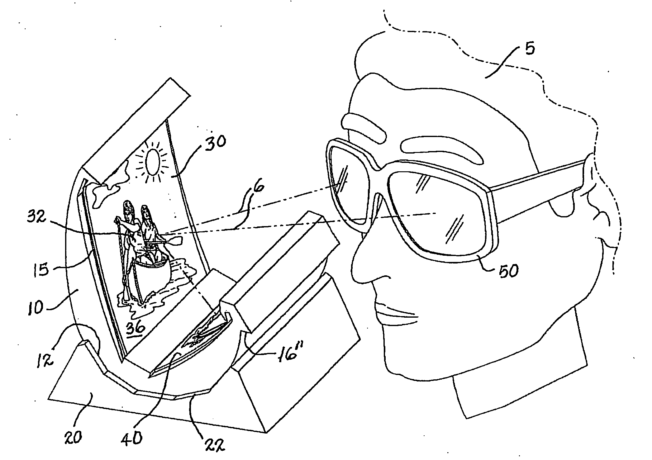
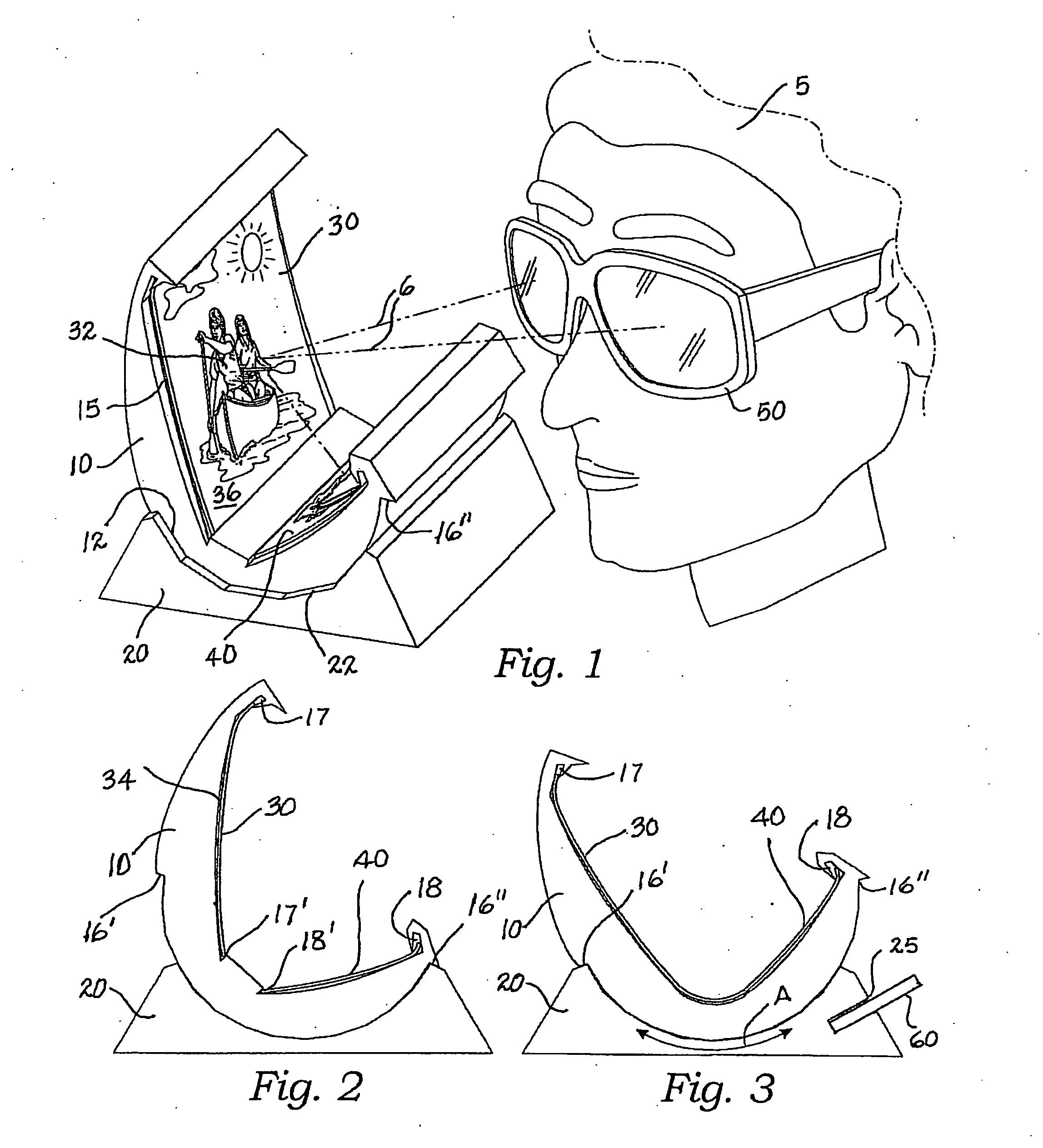
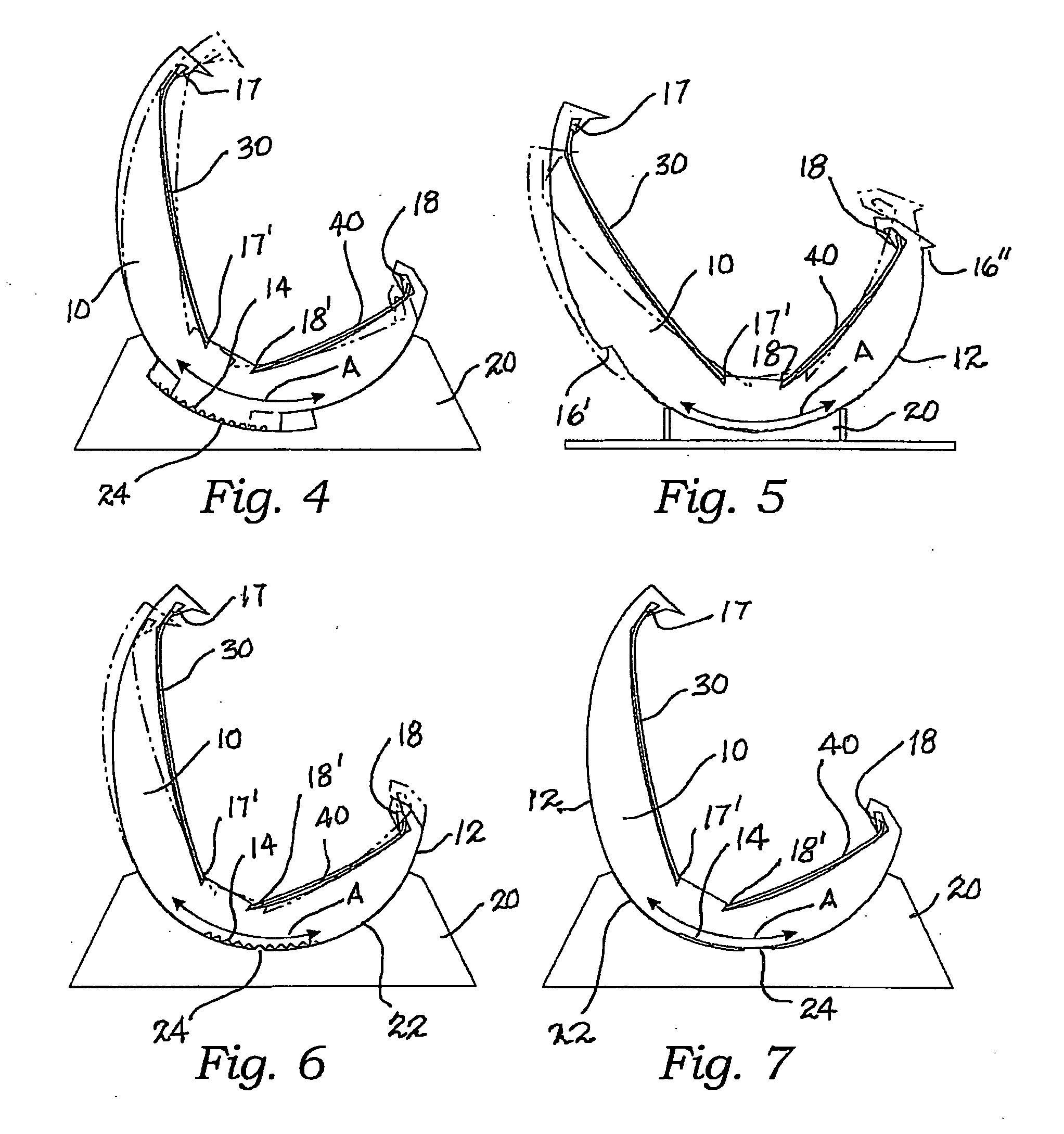
[0030]Described now in detail is an apparatus for demonstrating the effect of reducing glare using polarized lenses or other glare reducing filter. In this description, and the claims to follow, we use the example of polarized lenses and the polarizing effect as applied to glare reduction, but in all instances in this writing, “polarized lenses,” shall mean as well, any other type of glare reducing filte...


PUM


Abstract

A glare reducing lens is demonstrated by a holder with a half-mirrored plate and a graphic image mounted on the holder at an angle to the plate. The plate has another graphic image positioned behind it and visible through the plate. The holder is adapted for movement on the base over a range of positions for convenient viewing by tall and short persons. Such positioning of the holder is controlled by mechanical interconnecting surfaces. The viewer sees the graphic image transmitted through the mirrored plate as well as a superimposed image reflected onto the mirrored plate from the separate graphic image. When a viewer does not use a glare reducing lens, the two images visually interfere with each other, while by viewing through a lens the reflected image is eliminated leaving the directly viewed graphic image sharp and clear.

Description

CROSS-REFERENCE TO RELATED APPLICATIONS[0001]Not applicable.STATEMENT REGARDING FEDERALLY SPONSORED RESEARCH OR DEVELOPMENT[0002]Not applicable.THE NAMES OF THE PARTIES TO A JOINT RESEARCH AGREEMENT[0003]Not applicable.INCORPORATION-BY-REFERENCE OF MATERIAL SUBMITTED ON A COMPACT DISC[0004]Not applicable.REFERENCE TO A “MICROFICHE APPENDIX”[0005]Not applicable.BACKGROUND OF THE INVENTION[0006]1. Field of the Present Disclosure[0007]This disclosure relates generally to optical demonstration devices, apparatuses, and equipments, and more particularly to a demonstration stand for showing the benefits of polarized lenses to prospective customers interested in purchasing sunglasses.[0008]2. Description of Related Art including information disclosed under 37 CFR 1.97 and 1.98[0009]Bentley, U.S. Pat. No 6,808,394, discloses a system for demonstrating the effects of a polarized lens on reducing glare. The system includes a multi-layered light reflecting substrate having a visual indicia lay...

Claims


Application Information

Patent Timeline
Patent Type & Authority Applications(United States)
IPC IPC(8): G09B25/08
CPCG09B25/08
Inventor REIBER, PASCAL
Owner REIBER PASCAL
Why Eureka
Try Eureka