Targeting Device

a technology of a target device and a target body, which is applied in the field of target devices, can solve the problems of patient distress, femoral neck fracture and implant failure, and need for revision surgery

Inactive Publication Date: 2008-05-29
CHANA GURSHARAN SINGH
View PDF0 Cites 12 Cited by
  • Summary
  • Abstract
  • Description
  • Claims
  • Application Information

AI Technical Summary

Benefits of technology

This patent describes a targeting device for orthopedic surgery procedures. One aspect of this device includes one or more retractable arms that have sensors attached to them. These arms can extend out from a housing to provide precise positioning during surgery. Another part of the device is a sleeve-like structure that has room for the patient's femoral head and also contains the sensors used for accurate placement. Overall, this technology helps improve precision and efficiency when performing surgeries involving bones.

Problems solved by technology

The technical problem addressed by this patent is how to accurately determine the position of the center of the femoral neck and the centerline through the femoral neck during hip surgeries such as replacement and resurfacing procedures. This helps ensure proper alignment between the replaced parts and reduces the risks associated with incomplete accuracy, including femoral neck fracture and failed implants requiring revision surgery. A targeting device is proposed to address this issue regardless of whether the surgery involves minimal or traditional techniques.

Method used


Image

  • Targeting Device
  • Targeting Device
  • Targeting Device

Examples


Embodiment Construction

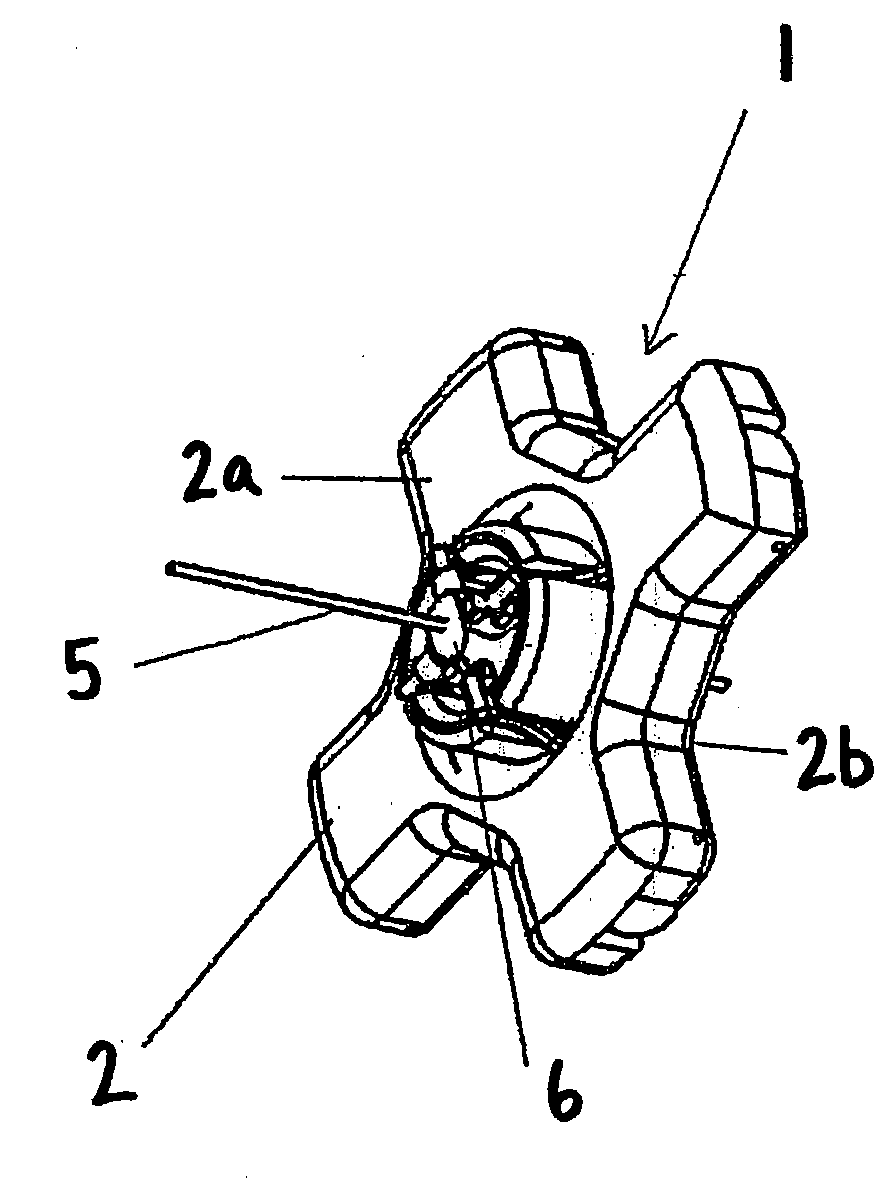
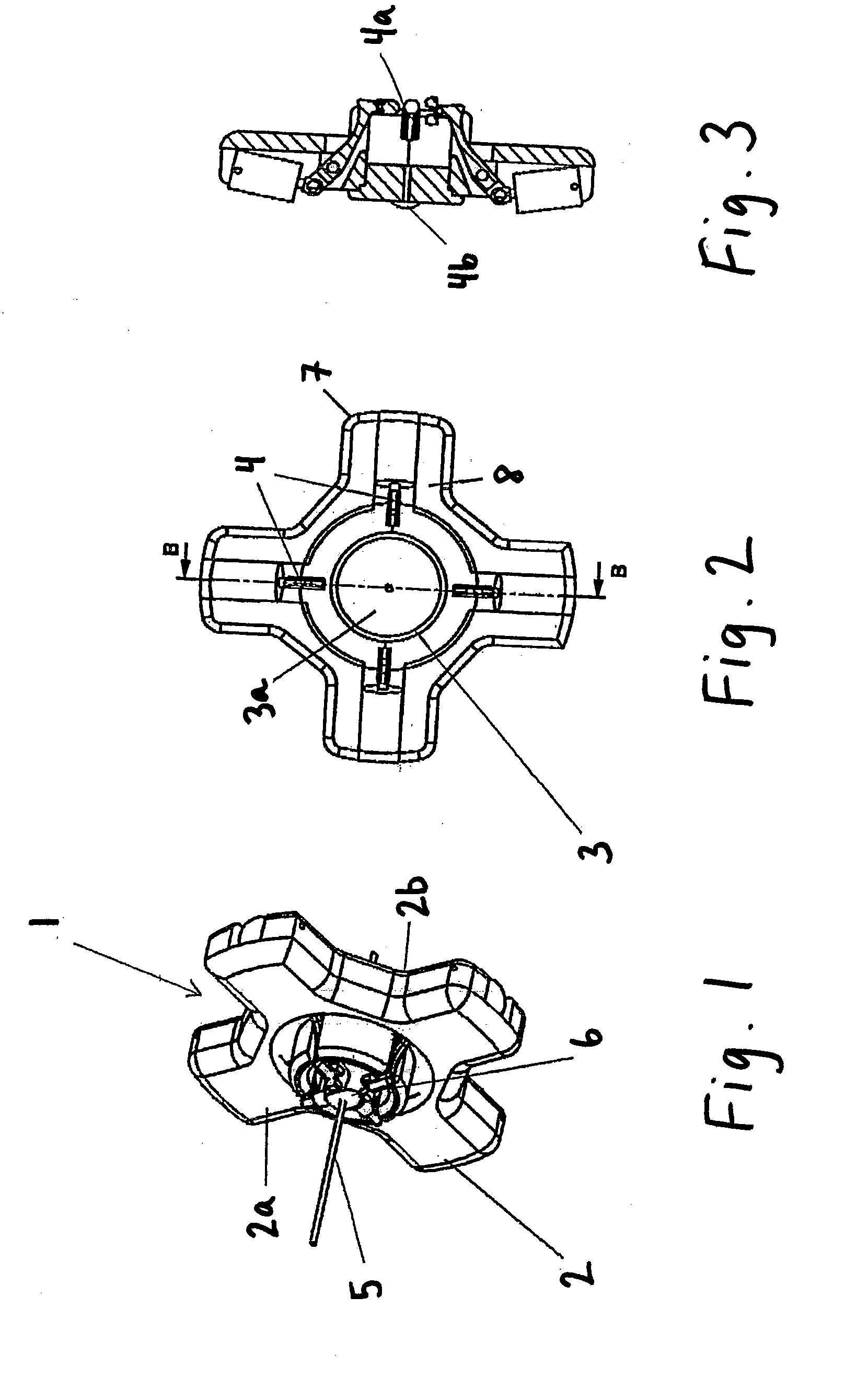
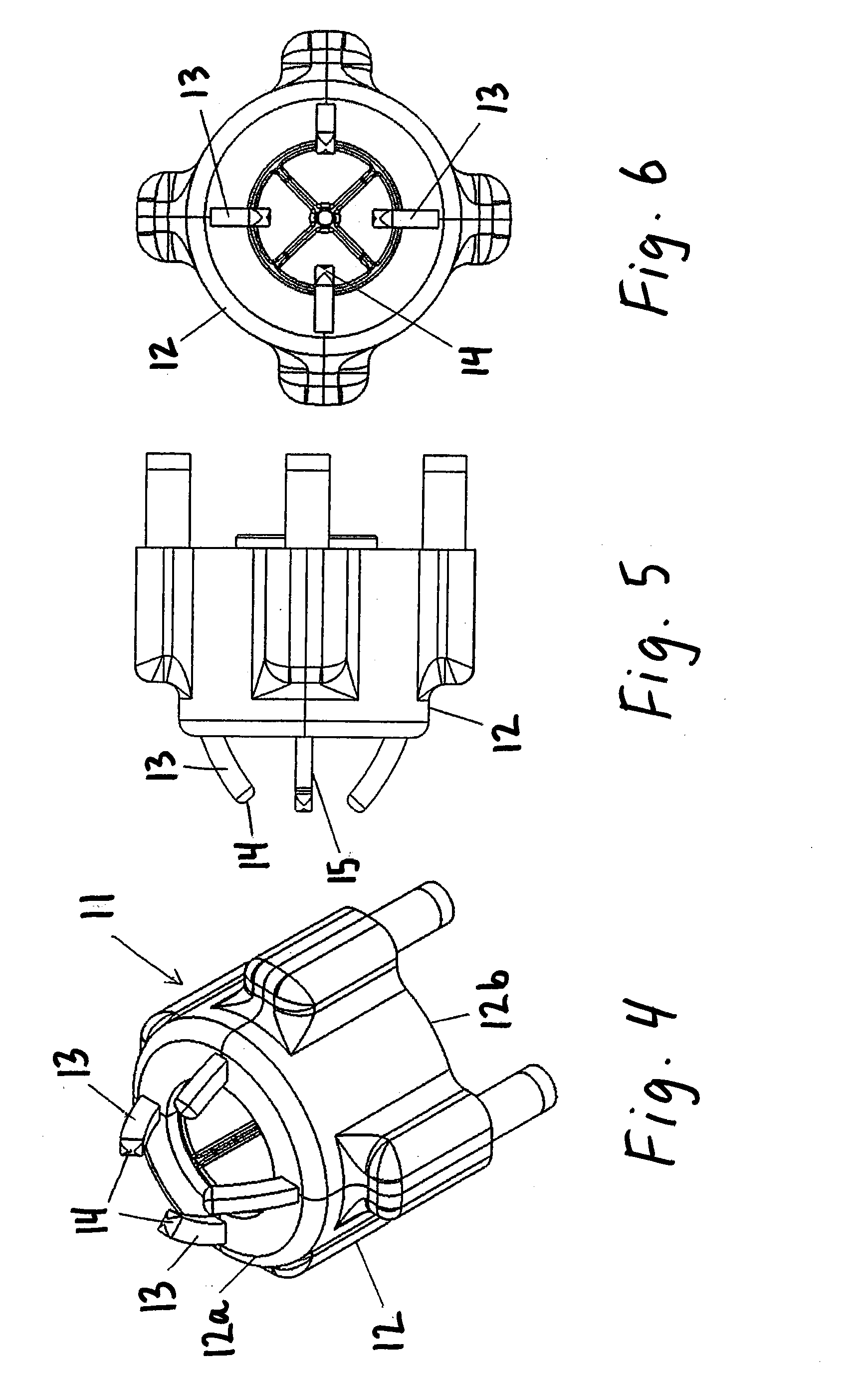
[0024]In an exemplary embodiment, there is provided a targeting device for use in hip surgery to allow the position of the centerline of the femoral neck to be located. The targeting device may comprise one or more sensor device that are moveable to a position inside the body that is over the femoral neck and radially spaced therefrom and that are suitable for obtaining data relating to the location of the surface of the femoral neck with respect to a reference position, in both the anterior-posterior and superior-inferior planes. The targeting device may also comprise a guide sleeve, having a bore capable of receiving a guide wire; a guide sleeve location adjustor, suitable for moving the guide sleeve in the anterior, posterior, medial and lateral directions; and a computer device with software for receiving data from the sensor device or devices and processing this data so as to determine the location of the centerline of the femoral neck.

[0025]The one or more sensor devices may b...


PUM


Abstract

A targeting device for use in hip surgery and more particularly for use in hip replacement surgery or hip resurfacing surgery, which may include minimally invasive surgery. An exemplary embodiment of the targeting device comprises one or more sensor devices, a guide sleeve, a guide sleeve location adjustor, and a computer device with software for receiving data from the sensor device or devices and processing this data so as to determine the location of the centerline of the femoral neck. In other embodiments, the sensor devices are movable so as to obtain data at two or more different radial locations around the femoral neck or angularly spaced in order to obtain data in the anterior-posterior plane and in the superior-inferior plane. Moreover, the sensor devices can be placed on retractable arms.

Description


Claims


Application Information

Patent Timeline
Owner CHANA GURSHARAN SINGH
Why Eureka
Try Eureka