
Self-retaining retractor for hip replacement surgery

a hip replacement and self-retracting technology, applied in the field of surgical devices, can solve the problemsclumsy use, and difficult and/or clumsy use of current self-retracting retractor systems, and achieves the effect of reducing the risk of fracture, and increasing the cost of surgery

Inactive Publication Date: 2015-04-30
BARNETT STEVEN L +1
View PDF3 Cites 11 Cited by
  • Summary
  • Abstract
  • Description
  • Claims
  • Application Information

AI Technical Summary

Benefits of technology

The invention relates to a surgical retractor for hip replacement surgery. The retractor comprises a pair of handles, a locking ratchet, and two arms. The arms have a modular blade system with an interchangeable blade and a female broach system. The retractor allows for self-retention and has improved stability and mobility during surgery. The technical effects of the invention are improved surgical accuracy and efficiency.

Problems solved by technology

The presence of assistants and retractors results in less room for the surgeon to operate, and increases the cost of the surgery.
Some current self-retaining retractor systems still take up much space and are difficult and / or clumsy to use.
Socket preparation in this manner is often difficult because the femur can be difficult to retract and blood egress from the femoral canal typically drains in the field of view.

Method used


Image

  • Self-retaining retractor for hip replacement surgery
  • Self-retaining retractor for hip replacement surgery
  • Self-retaining retractor for hip replacement surgery

Examples


Embodiment Construction

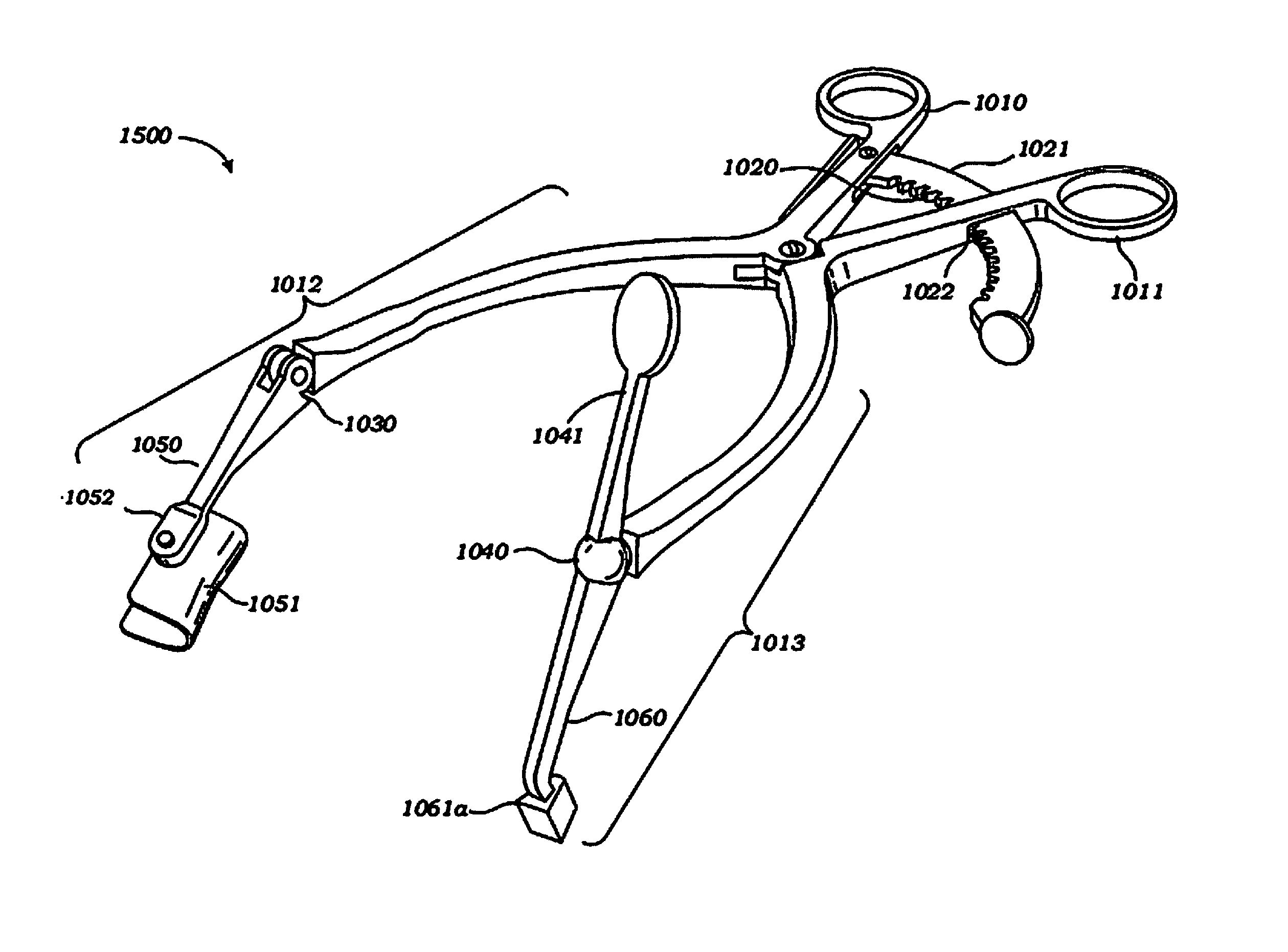
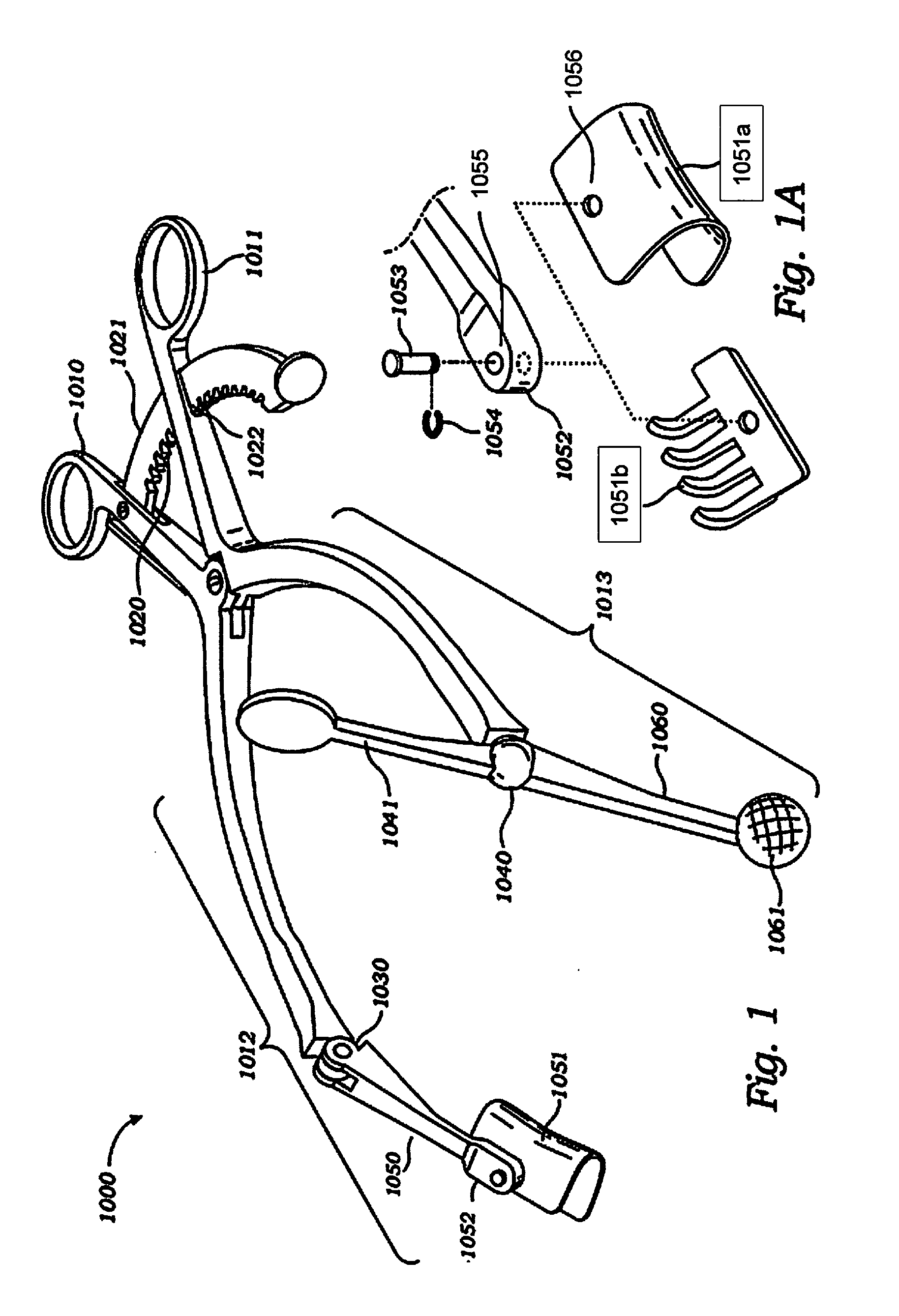
[0019]Turning to FIG. 1, according to an embodiment, an acetabular self-retaining retractor system 1000 is shown. The acetabular self-retaining retractor system 1000 generally comprises handles 1010, 1011 with finger rings, a locking ratchet 1020, an arm 1012 having a hinge joint 1030, an anterior capsule arm (or anterior retractor arm) 1050 and a modular blade system 1051, an arm 1013 having a universal locking joint 1040, with locking lever 1041, and a posterior retractor arm 1060 having a ball-tip 1061.

[0020]The acetabular self-retaining retractor system 1000 has an adjustable self-locking mechanism 1020. The self-locking mechanism 1020 includes a locking ratchet 1021 with a serrated (teeth) edge away from the finger rings of handles 1010, 1011. The locking ratchet 1021 has an end which is anchored in an elongated aperture on the inner side of the handle 1010, allowing the locking ratchet 1021 to pivot. The locking ratchet 1021 moves through an elongated aperture 1022 on the side...


PUM


Abstract

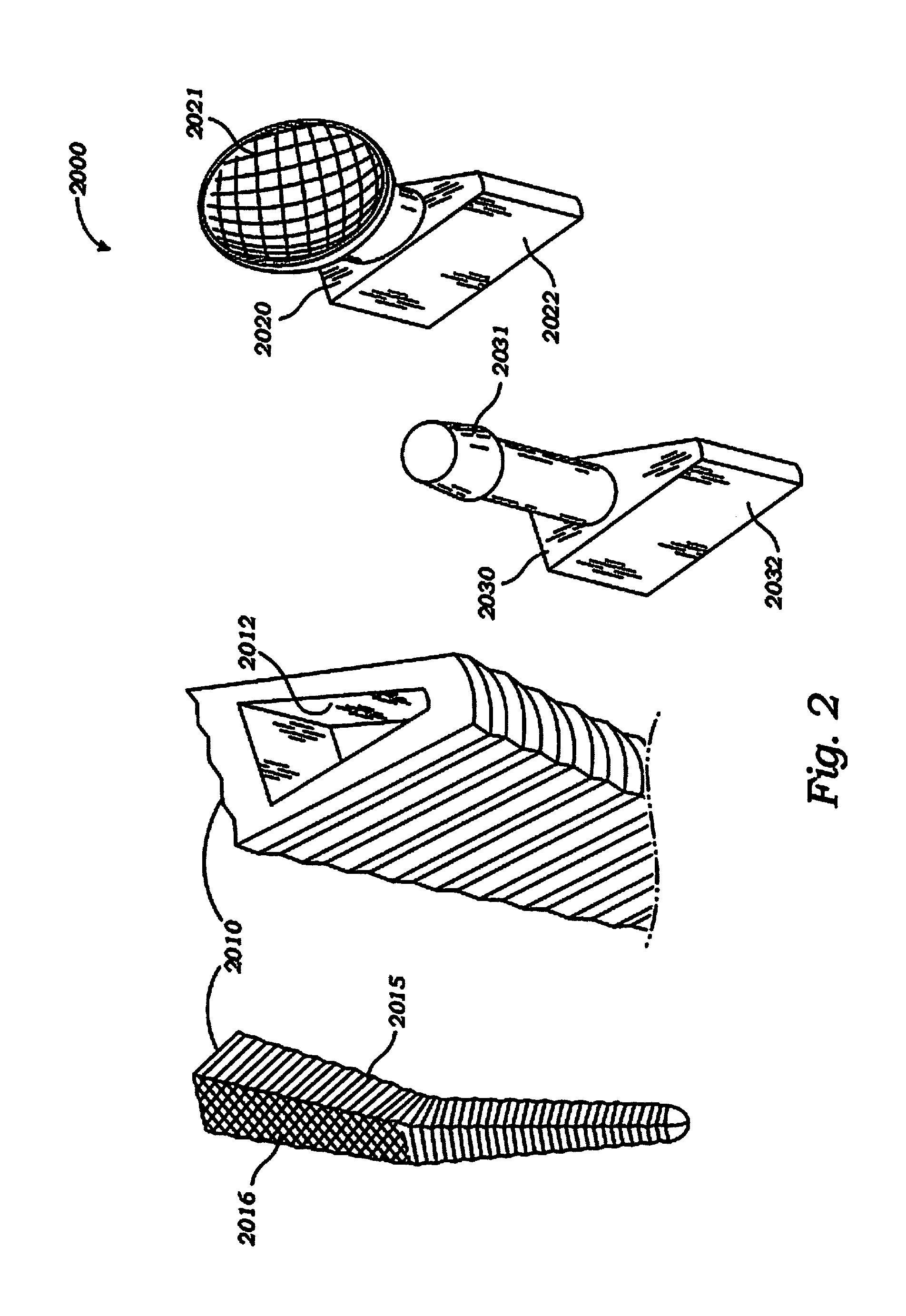
The field of the invention relates to systems and methods for surgical retractor, and more particularly to systems and methods for self-retaining retractor used in hip replacement surgery. In an embodiment, a retractor for surgery comprises a pair of handles, a locking ratchet, a first arm comprising a first portion, a hinge joint, and a second portion having a modular blade system; and a second arm comprising a first portion, a universal locking joint, a locking lever, and a second portion having a generally triangular shaped end. In an embodiment, the modular blade system has an interchangeable blade. In another embodiment, the second portion of the second arm has a ball shaped end. In another embodiment, the second portion of the second arm has a female end. In another embodiment, a female broach system comprises a female broach having a generally triangular aperture at one end, an extraction pattern on one side, and compaction pattern on the remaining sides; a male acetabular self-retaining broach insert; and a male trunion trial.

Description

FIELD OF THE INVENTION[0001]The field of the present invention generally relates to surgical devices, and more particularly to a self-retaining retractor used in hip replacement surgery.BACKGROUND OF THE INVENTION[0002]Total hip replacement surgery requires surgical exposure of the hip joint in order to insert the prosthetic replacement. Generally, in a total hip replacement surgery, the surgeon makes an incision opening approximately 10-30 cm long in various locations depending on which defined approach is being used to expose the joint. The incision is stretched open to 7 to 8 cm wide by using multiple surgical retractors. One or more surgical assistants are needed to hold these retractors to keep the incision open during the operation. To expose the acetabulum (hip socket), mobilization and retraction of the femur is necessary for visualization. Typically this is undertaken by placing multiple angled retractors over the rim of the socket. This is done using retractors of various ...

Claims


Application Information

Patent Timeline
Patent Type & Authority Applications(United States)
IPC IPC(8): A61B17/02
CPCA61B17/0206A61B2017/00477A61B2017/0275A61B2017/2837A61B17/1659A61B17/1668A61B17/2833A61B17/285A61B2017/00407A61B2017/00473
Inventor BARNETT, STEVEN L.FIRESTONE, THEODORE
Owner BARNETT STEVEN L
Learn More