
Automated machine repositioning in an excavating operation

a technology of automatic repositioning and excavating, which is applied in the direction of analogue processes, instruments, navigation instruments, etc., can solve the problems of operator fatigue, inability to achieve the most efficient repositioning of the tractor, and loss of time in the individual performance of the operator of the several steps

Inactive Publication Date: 2008-06-05
CATERPILLAR INC
View PDF68 Cites 46 Cited by
  • Summary
  • Abstract
  • Description
  • Claims
  • Application Information

AI Technical Summary

Benefits of technology

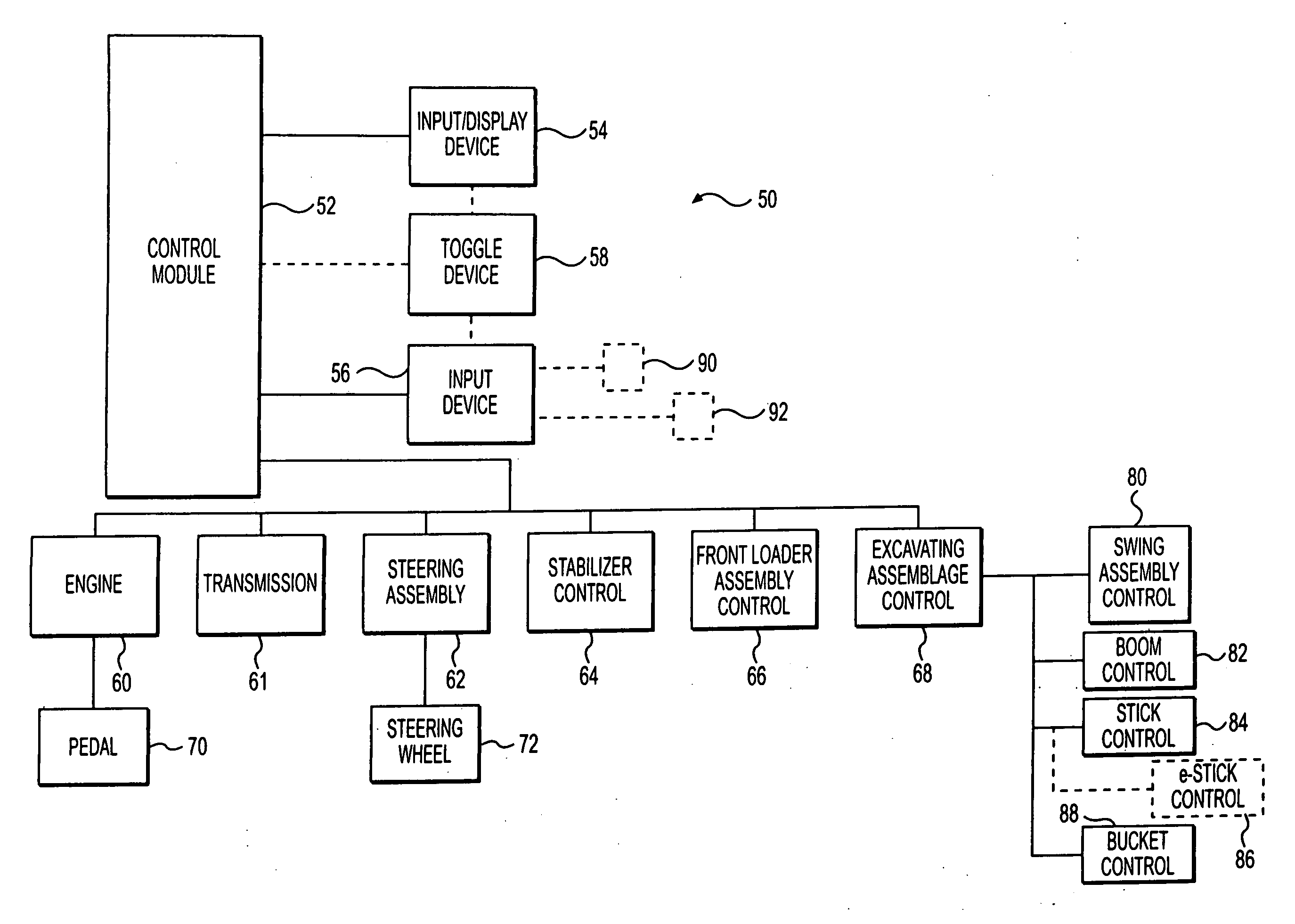
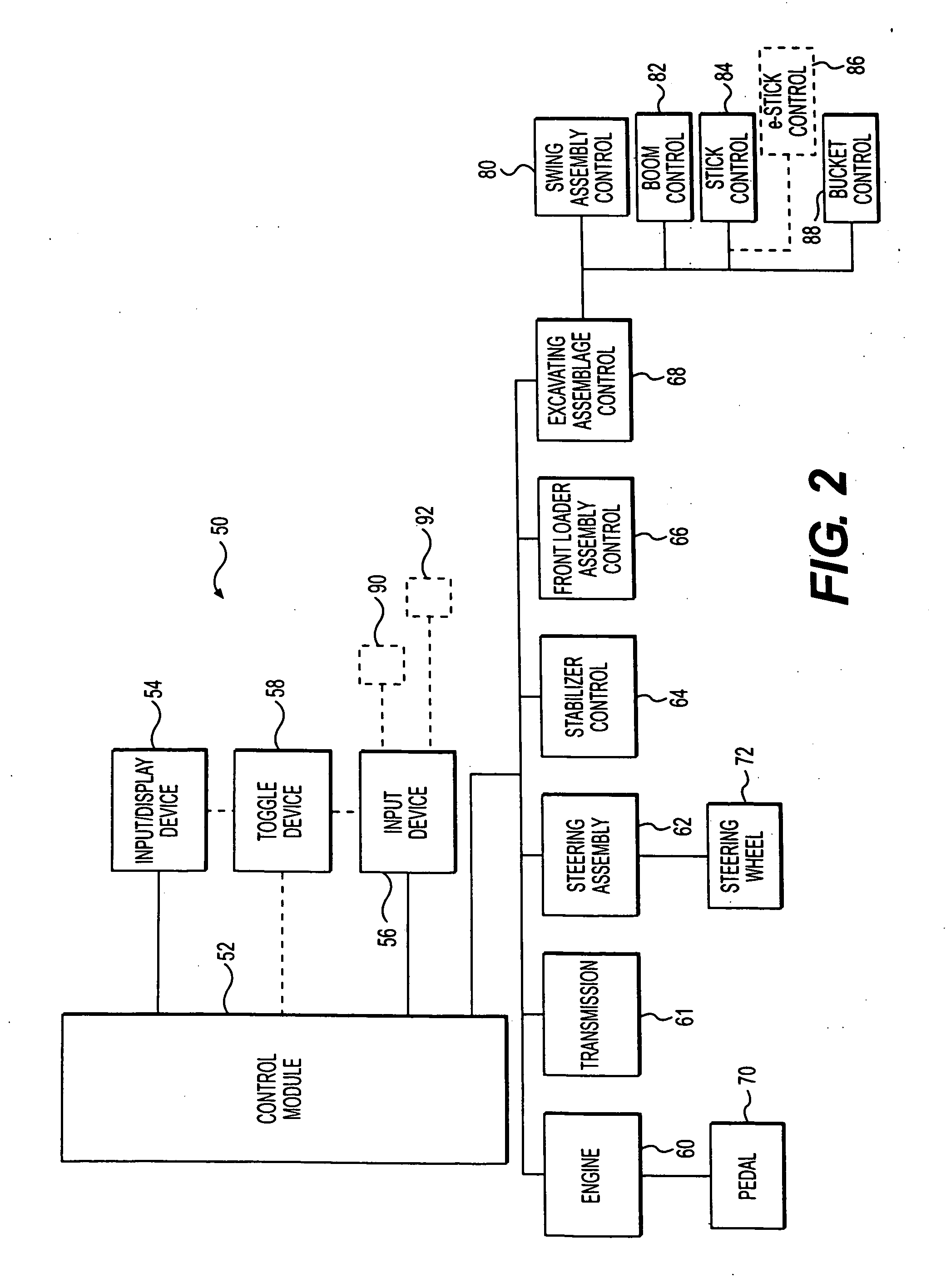
[0013]In one aspect, the present disclosure is directed to a method of repositioning a machine during an excavating operation from a first machine position to a second machine position. The method includes selecting a target distance to the second machine position. The method also includes activating an operator input device configured to send a control input signal to a control module to initiate a repositioning phase. The method further includes, during the repositioning phase, moving the machine toward the second position while maintaining operator control of movement, and determining when the machine has traveled the target distance. The method also includes stopping the machine under automated machine control at the second machine position.
[0014]In another aspect, the present disclosure is directed to a system for control of repositioning an excavator from a first set-up position from which a first excavating phase occurs, to a second set-up position from which a second excavating phase occurs. The system includes an excavating assemblage. The system also includes a control system including an input device configured to be selectively programmed to be manipulated by an operator to initiate and control machine movement during a repositioning phase, and a control module configured to deliver an output signal to stop the excavator at the second set-up position under automated machine control.

Problems solved by technology

Time may be lost in the individual performance by the operator of the several steps involved in machine movement.
Swiveling between the rear facing and front facing positions to individually manipulate the several controls involved in movement to a new set-up position may be yet one more factor contributing to operator fatigue.
Relying on the operator to determine the appropriate movement distance may not yield the most efficient repositioning of the tractor.
While the arrangement in the Anwar et al. patent may disclose automation of some work machine functions, the Anwar et al. patent does not recognize the adverse contribution to productivity that machine repositioning may have on the overall efficiency of an excavating operation.
In addition, the Anwar et al. patent does not disclose any particulars regarding machine repositioning or inefficiencies that may be incurred during machine repositioning.
Furthermore, the Anwar et al. patent does not disclose automation of the series of actions which may be included in a machine repositioning phase that may occur between excavating phases of an excavating operation.
Autonomous operation is difficult and expensive to achieve and, by itself, does not aid or serve as a solution to execution of machine repositioning.

Method used


Image

  • Automated machine repositioning in an excavating operation
  • Automated machine repositioning in an excavating operation
  • Automated machine repositioning in an excavating operation

Examples


Embodiment Construction

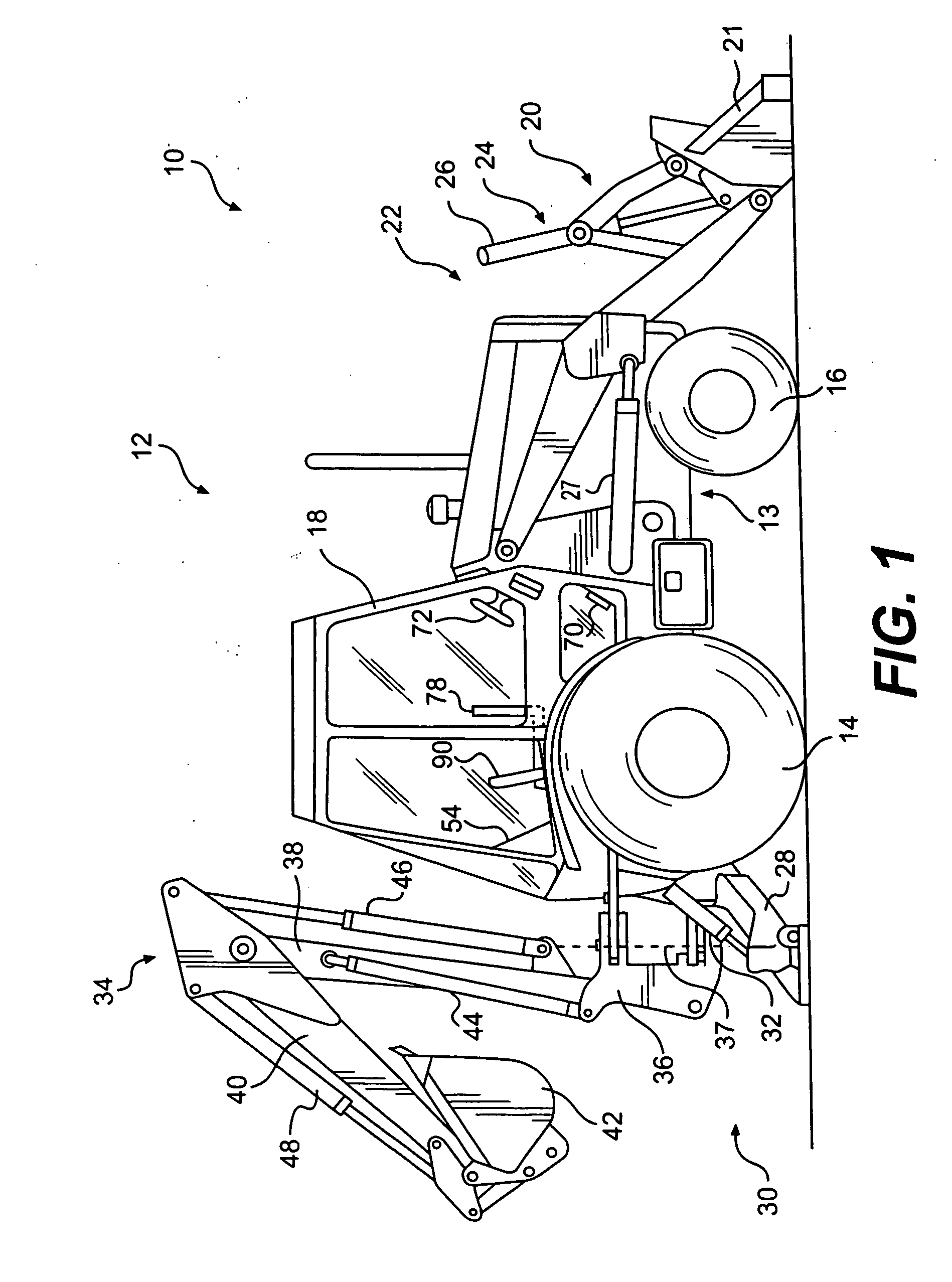
[0023]FIG. 1 illustrates an exemplary backhoe loader 10 that may be employed in connection with embodiments of the disclosure. Backhoe loader 10 may include a machine, such as a tractor 12. Tractor 12 may include a chassis 13 and a ground transportation assembly, including a pair of rear wheels 14 and a pair of front wheels 16 mounted to chassis 13. It should be understood that, instead of wheels 14 and 16, the tractor 12 could be provided with a pair of tracks or other structure to permit ground transportation. Backhoe loader 10 also may include a cab 18 or other suitable facilities to accommodate an operator and to house machine controls.

[0024]The backhoe loader 10 may include a front loader assembly 20 including a loader bucket 21 at a front end 22 of the tractor 12, and suitable operating linkage 24 for manipulation of the loader bucket 21 under the control of actuators 26 and 27, such as hydraulic cylinders. The backhoe loader 10 may include a pair of stabilizers, one of which ...


PUM


Abstract

A method of repositioning a machine during an excavating operation from a first machine position to a second machine position is provided. A target distance to the second machine position is selected. An operator input device configured to send a control input signal to a control module to initiate a repositioning phase is activated. During a repositioning phase, the machine is moved toward the second position while an operator maintains control of movement. A determination is made when the machine has traveled the target distance. The machine is stopped under automated machine control at the second machine position.

Description

TECHNICAL FIELD[0001]This disclosure relates to automated machine repositioning in an excavating operation and, more particularly, to a method and a system for at least partially automating actions involved in repositioning an excavating machine during an excavating operation.BACKGROUND[0002]Many machines have been developed for excavating. One commercially available type of machine often used for excavating, for example in a trenching operation, is a backhoe. Generally, a backhoe is mounted on a tractor or other machine body moveable along the ground on wheels or tracks. The backhoe may be the only excavating assemblage or handling implement on the tractor or machine body, or it may be one of a plurality of implements. For example, one relatively common machine, generally known as a backhoe loader, may include a backhoe mounted at one end of a tractor, and may include a loader bucket and accompanying operating linkage mounted at the other end of the tractor.[0003]A typical backhoe ...

Claims


Application Information

Patent Timeline
Patent Type & Authority Applications(United States)
IPC IPC(8): E02F3/32E02F1/00G06F19/00G01C21/00
CPCE02F9/2045E02F9/2004
Inventor STANEK, DANIELKOCH, ROGER D.ALIG, JEFFREY S.PRICE, ROBERT J.
Owner CATERPILLAR INC
Learn More