

Workpiece dividing method utilizing laser beam
a technology of laser beam and workpiece, which is applied in the direction of glass making apparatus, manufacturing tools, welding/soldering/cutting articles, etc., can solve the problems of voids and cracks, small width of the resulting groove, and relatively low percentage of the area usable for semiconductor circuit formation
- Summary
- Abstract
- Description
- Claims
- Application Information
AI Technical Summary
Benefits of technology
Problems solved by technology
Method used
Image

Examples
example 1
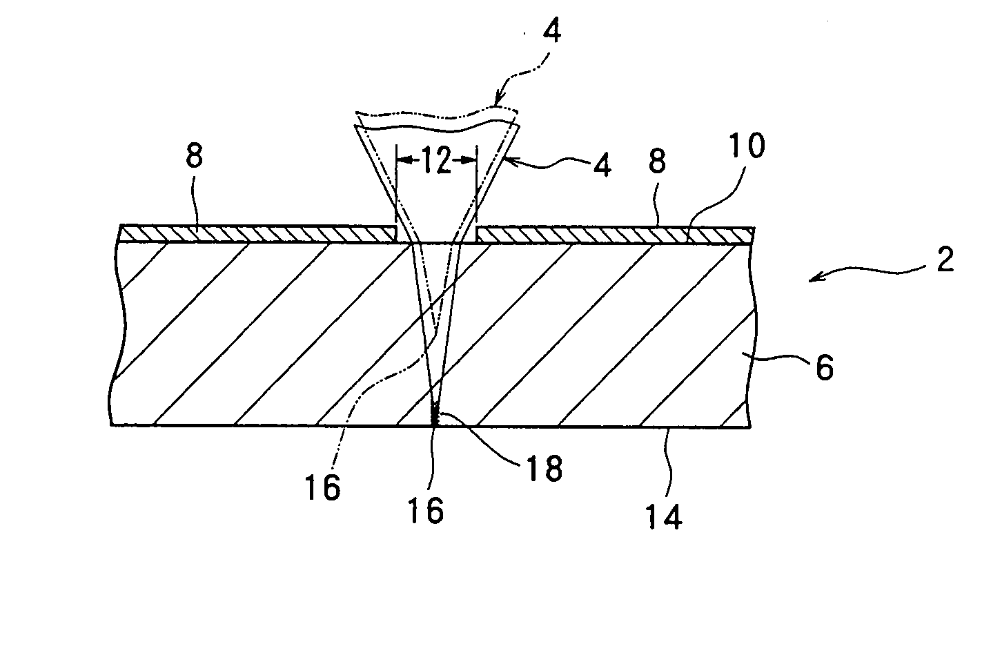
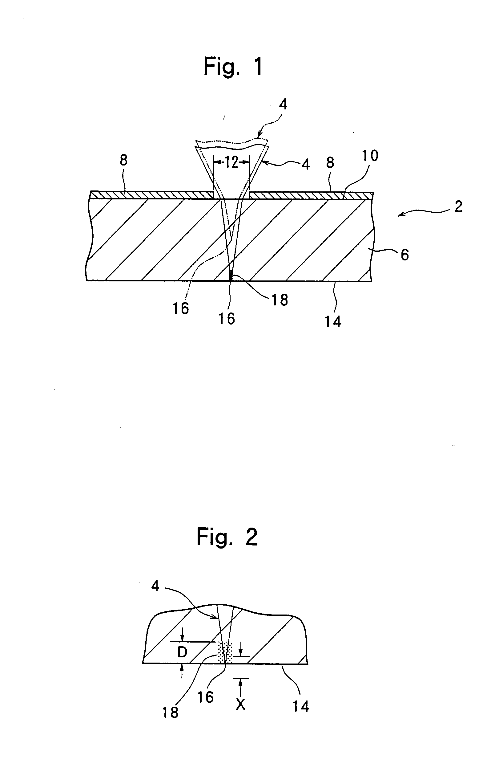
[0027]A sapphire substrate with a diameter of 2 inches (5.08 cm) and a thickness of 100 μm was used as a workpiece. In accordance with the mode illustrated in FIGS. 1 to 3, a laser beam was applied from one surface side of the workpiece, namely, from above, to generate a deterioration region along a predetermined division line. The application of the laser beam was performed under the following conditions, with the focused spot, i.e. focal point, of the laser beam being located on the other surface, i.e. lower surface, of the workpiece:
Laser
[0028]YVO4 pulse laser
[0029]Wavelength: 1064 nm
[0030]Spot diameter of focused spot: 1 μm
[0031]Pulse width: 25 ns
[0032]Peak power density of focused spot: 2.0×10¹¹ W / cm2
[0033]Pulse repetition frequency: 100 kHz
[0034]Speed of relative movement of laser beam (movement relative to the workpiece): 100 mm / second
[0035]Then, the workpiece was gripped manually, and a bending moment was applied thereto about the division line to break the workpiece along ...
example 2
[0036]The laser beam was applied in the same manner as in Example 1, except that after each movement of the laser beam relative to the workpiece along the division line, the position of the focused spot of the laser beam was displaced upward by 10 μm and, in this state, the laser beam was reciprocated twice (accordingly, moved 4 times) relative to the workpiece.
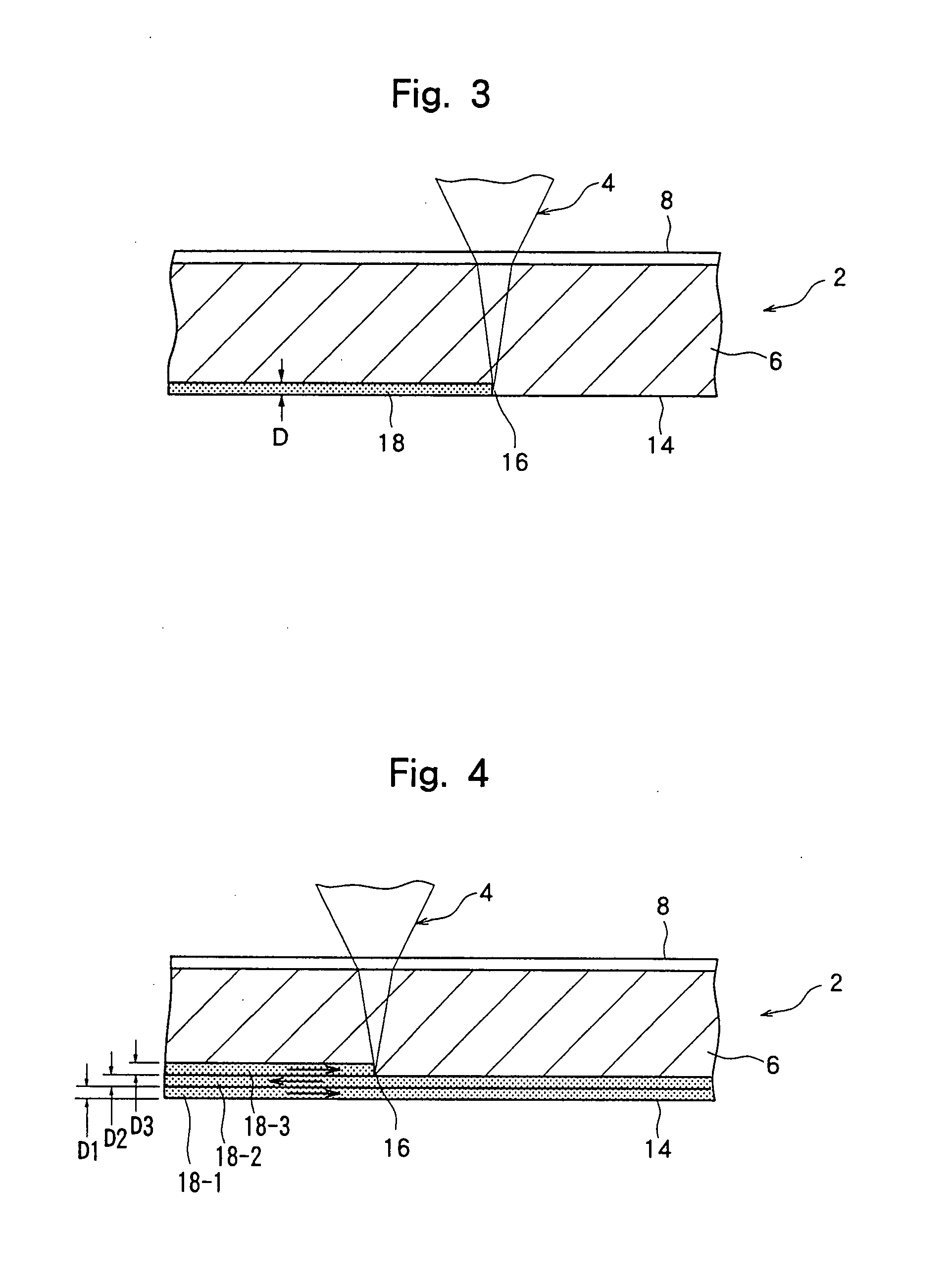
[0037]Then, the workpiece was gripped manually, and a bending moment was applied thereto about the division line to break the workpiece along the division line. Breakage was performed sufficiently precisely along the division line, and no marked fracture or the like was present at the break edge. FIG. 6 is a sketch of a photomicrograph (magnification ×200) of the break edge of the workpiece. As understood from FIG. 6, a deterioration region 18 of a depth of 40 to 50 μm was generated on the other surface side of the workpiece. Such a deterioration region was substantially free of voids or cracks.
PUM
 Abstract
Description
Claims
Application Information