Method for effectively segmenting hyperspectral oil-spill image

A hyperspectral oil spill image technology, which is applied in the field of hyperspectral oil spill image segmentation, can solve problems such as difficult segmentation effects, hyperspectral oil spill images containing bright spots, and uneven gray levels of oil spill images

Inactive Publication Date: 2017-02-22
DALIAN MARITIME UNIVERSITY
View PDF4 Cites 19 Cited by
  • Summary
  • Abstract
  • Description
  • Claims
  • Application Information

AI Technical Summary

Problems solved by technology

The hyperspectral oil spill image has the following characteristics: (1) Due to the diffusion of the oil area, the thickness of the oil film in the boundary area is thin, and the interaction with the seawater makes the boundary of the oil area in the image blurred, so it is not suitable to use the boundary-based segmentation algorithm; (2) The presence of factors such as sea surface reflections and fog makes the difference in the spectral curves corresponding to oil and water in the oil spill image smaller, which increases the difficulty of hyperspectral oil spill image segmentation
(3) Due to the defects of the equipment itself and the influence of other environmental factors such as light, the oil spill image often has grayscale inhomogeneity, which further increases the difficulty of segmentation
(4) Affected by sunlight and sea waves, hyperspectral oil spill images generally contain bright spots and shadow noise, so it is not suitable to use pixel-based segmentation methods such as clustering and thresholding, but active contours and region growth should be selected Region-Based Segmentation Algorithm
But despite this, the CV model or even any other segmentation method is not universal for all images, especially for remote sensing oil spill images with blurred boundaries, gray inhomogeneity, low contrast, and noise. achieve better segmentation

Method used


Image

  • Method for effectively segmenting hyperspectral oil-spill image
  • Method for effectively segmenting hyperspectral oil-spill image
  • Method for effectively segmenting hyperspectral oil-spill image

Examples


Embodiment Construction

[0090] The present invention will be further described below in conjunction with the accompanying drawings. Specific embodiments of the present invention will be described below based on simulated hyperspectral image and real hyperspectral image data respectively.

[0091] 1. Simulated hyperspectral image experiment

[0092] In order to verify the feasibility and effectiveness of the model, the experiment is first carried out on the simulated hyperspectral image, and the specific steps are as follows:

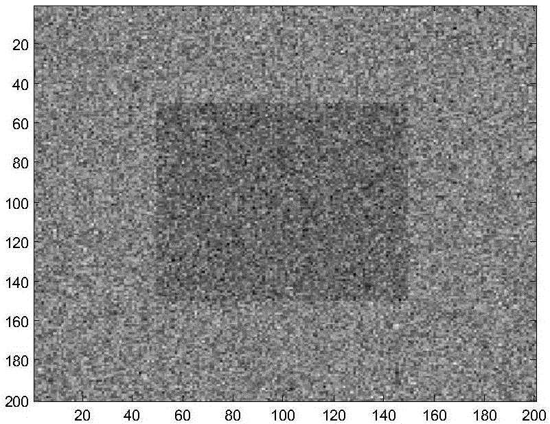
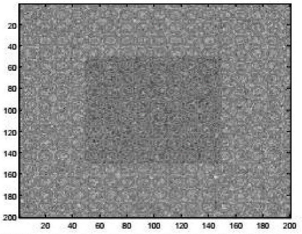
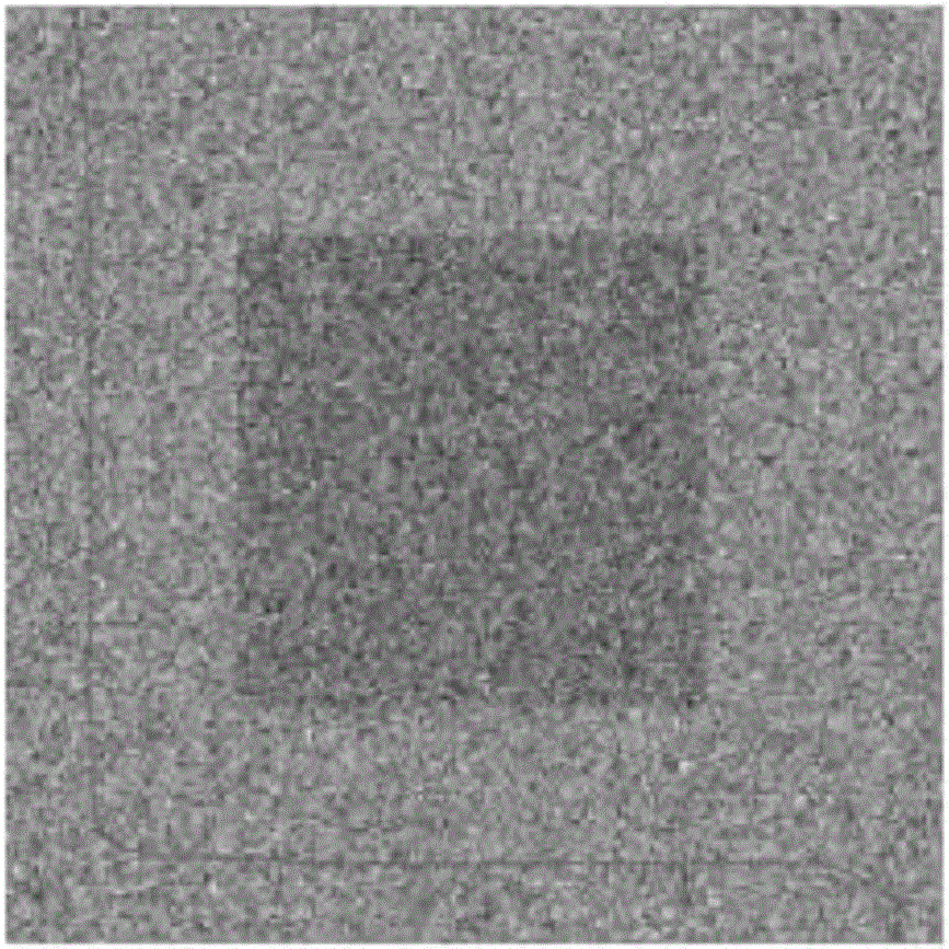
[0093] A. Synthetic hyperspectral simulated oil spill images

[0094] First, extract oil endmembers and water endmembers from real hyperspectral oil spill images, and then synthesize a simulated hyperspectral image with a size of 200×200 and a number of bands of 258, in which the 100×100 part in the middle of the image is composed of oil endmembers , the other parts are composed of water endmembers, and finally adding noise with a certain signal-to-noise ratio (SNR, Signal Nois...


PUM


Abstract

Provided is a method for effectively segmenting a hyperspectral oil-spill image. The method comprises steps of: defining an initial level set function and other related functions; acquiring a new fitting item in combination with a Fisher criterion; constructing an edge stop function to obtain a new length item; performing improvement in combination with an end member extraction algorithm; introducing a level set regular item to prevent reinitialization of the level set function; minimizing an energy function to obtain an Euler-Lagrange equation; setting parameters; selecting a display band and an initial contour; displaying a segmentation result graph; calculating various segmentation precision evaluation indexes; comparing and evaluating the accuracy of the segmentation results. The method can classify a target area in a simulated hyperspectral image and a real hyperspectral image, and effectively segments the hyperspectral oil-spill image with boundary blur and noise, improves the segmentation accuracy of the hyperspectral image, obtain a more accurate classification effect, makes the parameter change more stable, makes the contour curve more accurate, obtains the continuous and closed boundary contour, and has higher precision of segmentation.

Description

technical field [0001] The invention relates to a remote sensing image processing technology, in particular to a hyperspectral oil spill image segmentation method. Background technique [0002] The development of remote sensing technology has gone through panchromatic (black and white), color photography, multispectral scanning imaging, and the current stage of hyperspectral remote sensing. In short, hyperspectral remote sensing technology is a technology that continuously images ground objects with narrow and continuous spectral channels. new features. [0003] Segmentation or classification algorithms commonly used in hyperspectral images include threshold segmentation, clustering, region growing, support vector machines, and active contours. The hyperspectral oil spill image has the following characteristics: (1) Due to the diffusion of the oil area, the thickness of the oil film in the boundary area is thin, and the interaction with the seawater makes the boundary of t...

Claims


Application Information

Patent Timeline
Patent Type & Authority Applications(China)
IPC IPC(8): G06T7/136
CPCG06T2207/10036
Inventor 宋梅萍林彬蔡刘芬安居白张建袆
Owner DALIAN MARITIME UNIVERSITY
Why Eureka
Try Eureka