Stacked Heat Exchanger System with Swing-Out Heat Exchangers

a heat exchanger and heat exchanger technology, applied in indirect heat exchangers, machines/engines, light and heating apparatus, etc., can solve the problems of prolonging the useful life and affecting the efficiency of the heat exchanger

Active Publication Date: 2008-06-12
DEERE & CO
View PDF26 Cites 32 Cited by
  • Summary
  • Abstract
  • Description
  • Claims
  • Application Information

AI Technical Summary

Problems solved by technology

When heat exchangers are installed on heavy equipment, the heat exchangers may be subjected to vibration.
Vibrational isolators abso

Method used


Image

  • Stacked Heat Exchanger System with Swing-Out Heat Exchangers
  • Stacked Heat Exchanger System with Swing-Out Heat Exchangers
  • Stacked Heat Exchanger System with Swing-Out Heat Exchangers

Examples


Embodiment Construction

[0027]The embodiments disclosed below are not intended to be exhaustive or limit the invention to the precise forms disclosed in the following detailed description. Rather, the embodiments are chosen and described so that others skilled in the art may utilize their teachings.

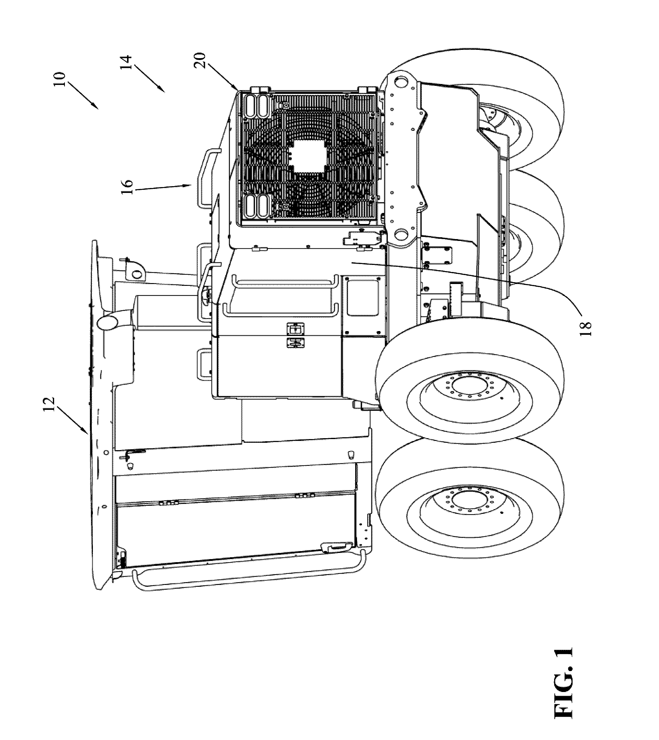
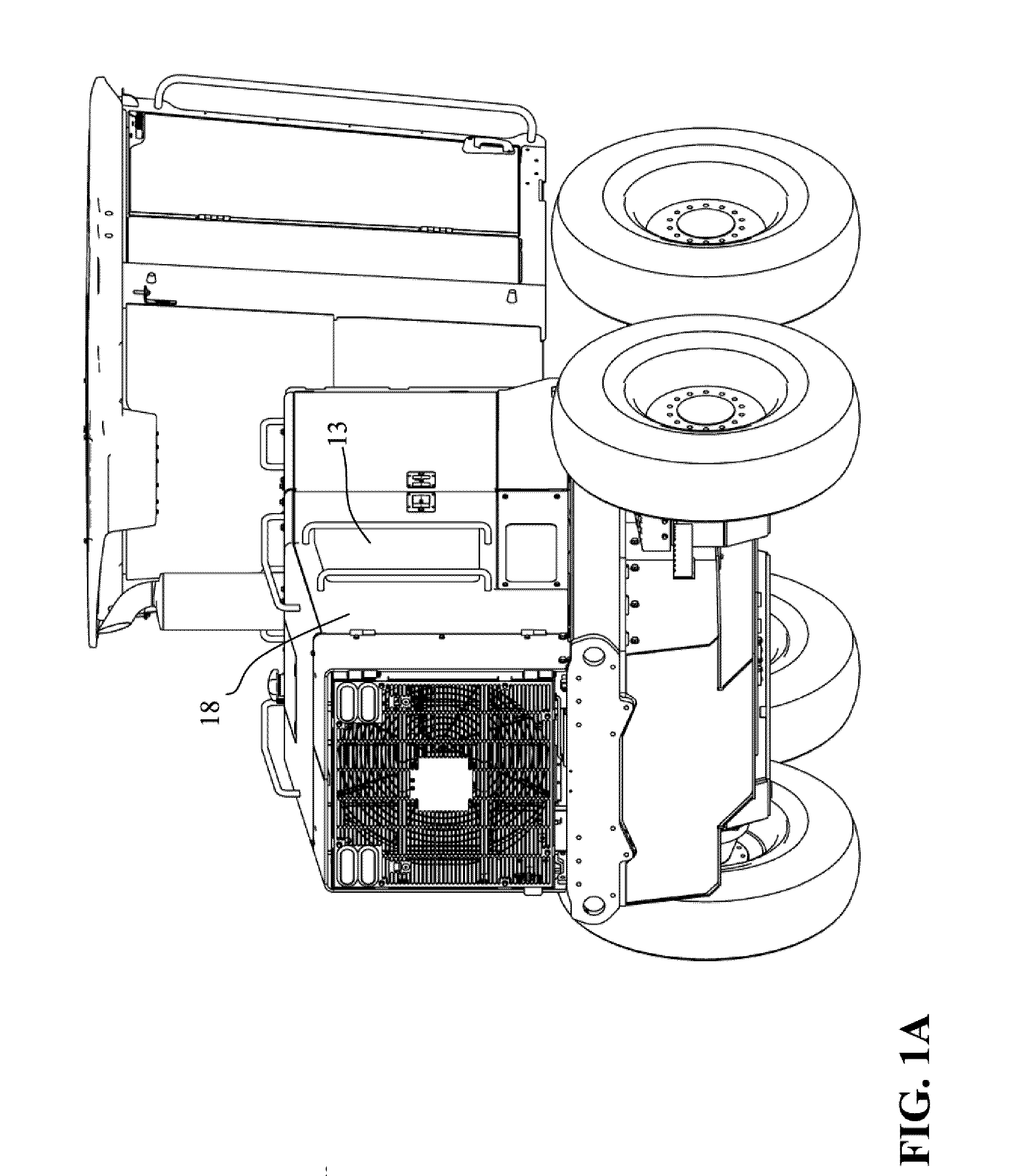
[0028]Referring initially to FIG. 1, one embodiment of heavy equipment is shown. Rear engine and cab portion of motor grader 10 includes cab 12 and rear body 14. Back portion 16 of rear body 14 houses heat exchanger system 20. In this illustrative embodiment, back portion 16 includes rear door assembly 18 which may be rotated outward to allow access to internal components of motor grader 10. In the illustrative embodiment, only a single rear door assembly 18 is shown. However, it should be understood that any suitable arrangement of housing affecting access to the heat exchanger system and individual components thereof may be used.

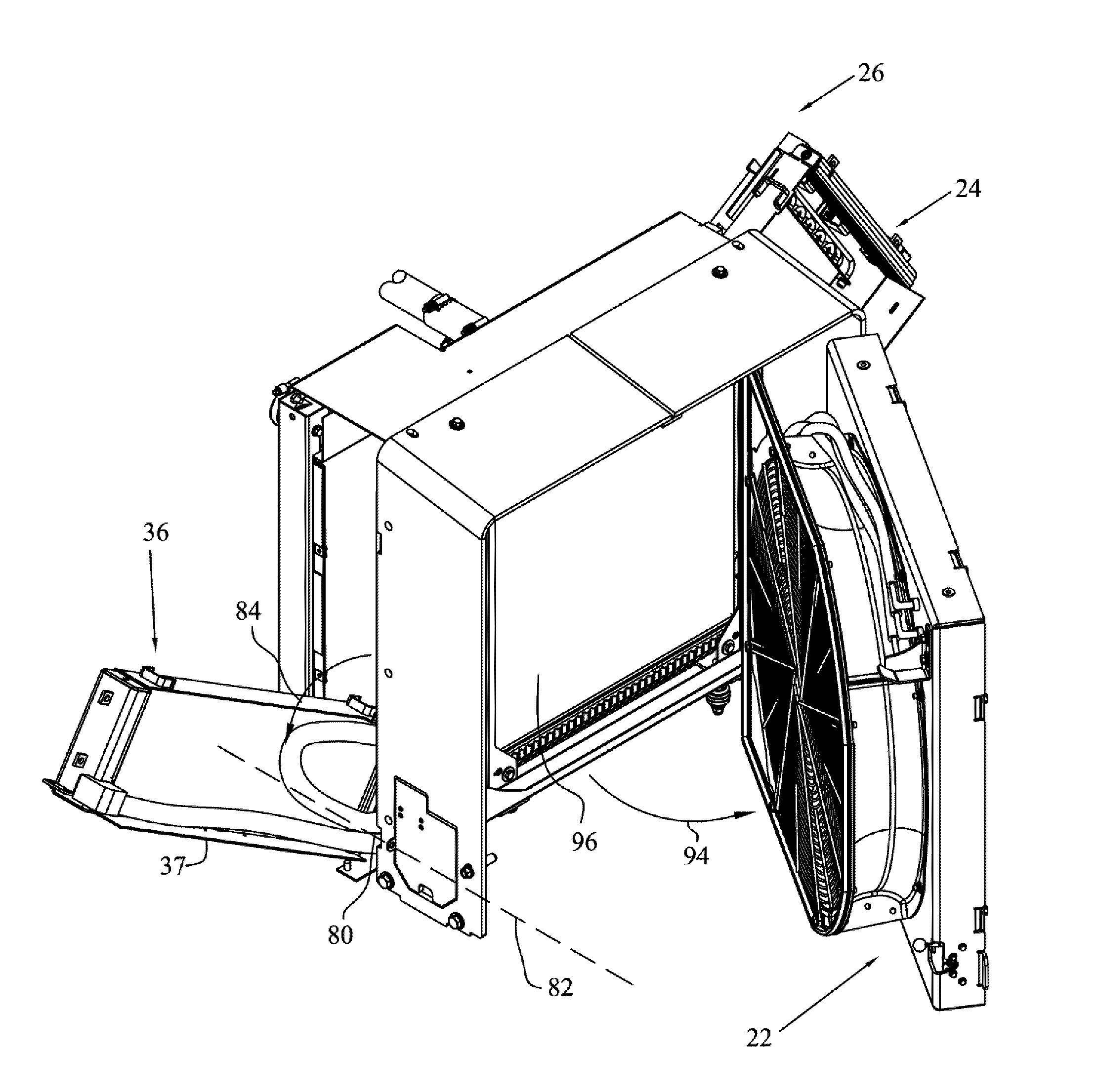
[0029]Referring now to FIG. 2, an exploded view of heat exchanger system 20 is sho...


PUM


Abstract

A heat exchanger system for use with heavy equipment including a heat exchanger rotatable about a horizontal axis out of a frame.

Description

[0001]This application is related to U.S. Provisional application Ser. No. 60 / 869,469 filed Dec. 11, 2006, the disclosure of which is expressly incorporated by reference herein.FIELD OF THE INVENTION[0002]The present invention is related to a heat exchanger system for heavy equipment such as a motor grader or an agricultural tractor. Specifically, the present invention is related to a heat exchanger system with swing-out heat exchangers.BACKGROUND OF THE INVENTION[0003]Typically, heavy equipment such as motor graders and wheel loaders are powered by one or more diesel or gasoline powered internal combustion engines. Generally, these engines are liquid cooled, however, air or air / oil cooled engines may also be used. Most liquid cooled engines include a heat exchanger system, the heat exchanger system including a coolant pump and a fan cooled heat exchanger. The term cooler can be used interchangeably with heat exchanger. Coolant passes through the heat exchanger and is cooled by air ...

Claims


Application Information

Patent Timeline
IPC IPC(8): F28F13/12
CPCB60K11/04B60K11/08F01P2070/52F28F2280/105F28D2021/0094F28F9/002F28D1/0443
Inventor LOWE, JARED JAYSONCOCAYNE, MICHAEL JOHNSASS, STEVEN RICHARDVIZE, AUSTIN EDWARD
Owner DEERE & CO
Why Eureka
Try Eureka