Apparatus and Method of Solid-State Welding

a technology of solid-state welding and soldering apparatus, applied in the direction of soldering apparatus, manufacturing tools, auxilary welding devices, etc., can solve the problem of not being able to accurately measure the depth of plung

Inactive Publication Date: 2008-06-12
GM GLOBAL TECH OPERATIONS LLC
View PDF8 Cites 36 Cited by
  • Summary
  • Abstract
  • Description
  • Claims
  • Application Information

AI Technical Summary

Benefits of technology

[0017]The above features and advantages, and other features and advantages, of the present invention are readily apparent from the following detailed description of the preferred embodiments and best modes for carrying out the invention when taken in connection with the accompanying drawings.

Problems solved by technology

However, in these traditional friction stir spot weld methods, a “plunge depth” that is not a true depth of plunge is programmed.

Method used


Image

  • Apparatus and Method of Solid-State Welding
  • Apparatus and Method of Solid-State Welding
  • Apparatus and Method of Solid-State Welding

Examples


Embodiment Construction

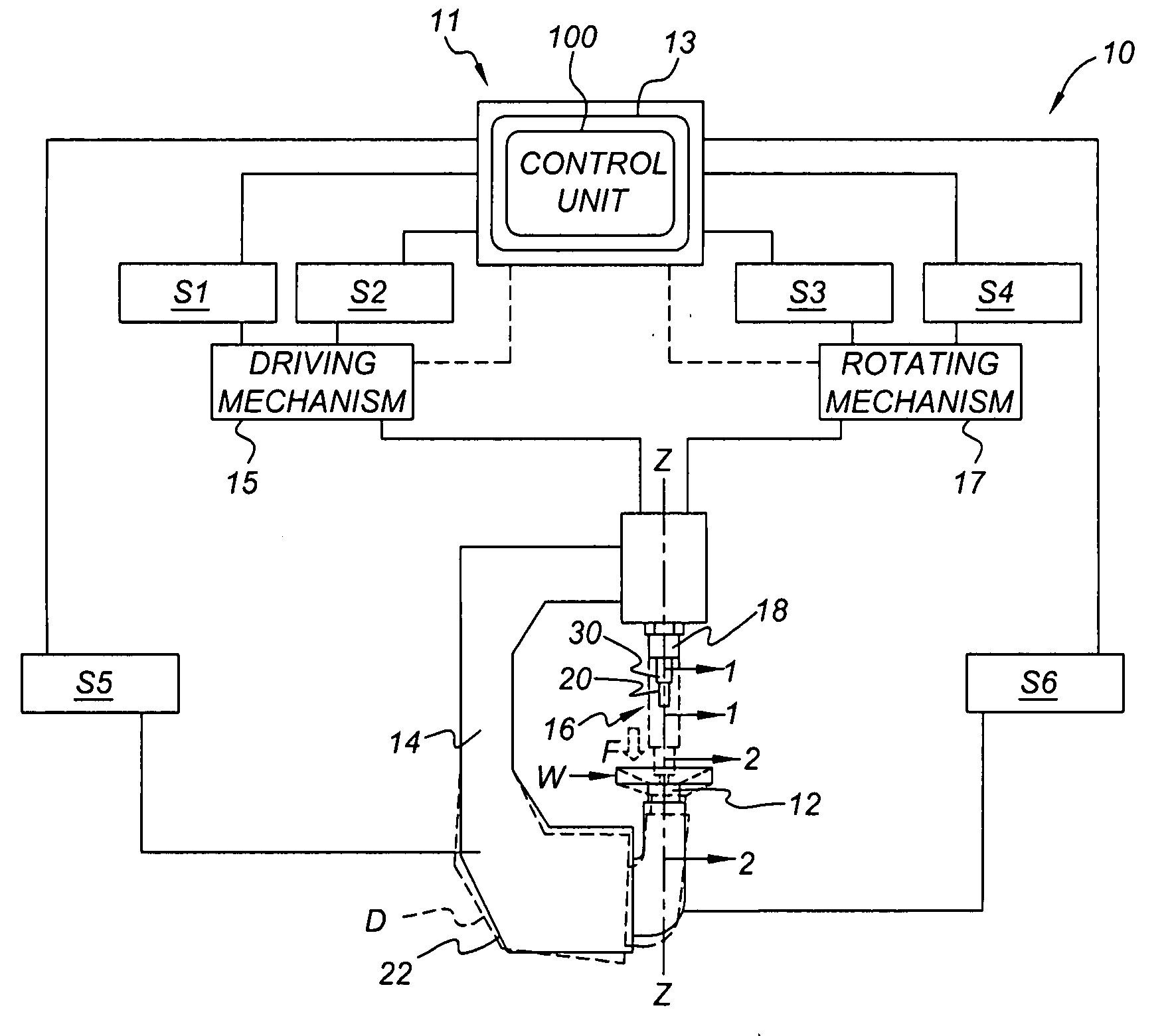
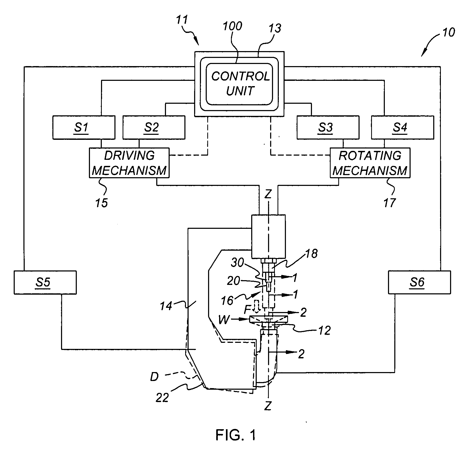
[0024]Referring to the figures, wherein like reference numbers refer to like components throughout the several views, there is shown a friction stir spot welding (FSSW) system or apparatus, partially illustrated and identified generally in FIG. 1 as element 10. The present invention will be described herein with respect to the FSSW apparatus 10 as an exemplary application by which the present invention may be incorporated; the present invention by no means being limited to the particular configuration or structure of FIGS. 1-4. To that extent, the present invention can be used in a variety of manufacturing processes. By way of example, the apparatus and method provided herein can be employed for operating on a single workpiece, for joining two or more workpieces together, or for joining two ends of a single workpiece together, as will be explained in detail hereinafter. In addition, the present invention can be applied in both 2-dimensional and 3-dimensional applications.

[0025]The F...


PUM

PropertyMeasurementUnit
forceaaaaaaaaaa
thicknessaaaaaaaaaa
thicknessaaaaaaaaaa

Abstract

The present invention provides an apparatus and improved method of friction stir spot welding that assures a predetermined bottom thickness and a reduction in variation in a series of resultant spot welds. The advantage of the present invention lies in that the plunge distance is controlled from the top plane of the anvil against which the bottom thickness is specified, and systematically adjusted to account for changing system parameters, such as, but not limited to, deflection and thermal expansion of the weld gun. The present invention also provides for improved and controlled weld quality through implementation of a dwell operation or dwell operations, whereby weld heat input is manipulated by causing the weld tool to dwell in a dwell region or at a desired depth or depths within the workpiece(s) for a predetermined time interval to achieve desired mechanical properties of the resultant weld joint.

Description

CLAIM OF PRIORITY[0001]This application claims priority to U.S. Provisional Patent Application No. 60 / 869,626, filed on Dec. 12, 2006, which is hereby incorporated by reference in its entirety.TECHNICAL FIELD[0002]The present invention relates to methods of solid-state welding for joining two or more workpieces or for operating on a single workpiece, and an apparatus for using the same.BACKGROUND OF THE INVENTION[0003]Welding is a manufacturing or fabrication process that bonds materials, usually metals or thermoplastics, by causing coalescence—the process by which two separate units grow together, fuse, or merge into a single body. The materials are joined by liquefying or plasticizing (e.g., soften without liquefying) the areas to be bonded together, generally through the application of heat and / or pressure over time, promoting coalescence of the liquefied or plasticized material, and allowing the coalesced material to cool, thereby solidifying the bond. Welding can be used, for e...

Claims


Application Information

Patent Timeline
Patent Type & Authority Applications(United States)
IPC IPC(8): B23K20/12
CPCB23K20/1235
Inventor CHEN, YEN-LUNGHALL, MARK T.TOTTEN, ROBERT L.SZYMANSKI, ROBERT T.GAYDEN, XIAOHONG Q.FISCHER, GREGORY A.
Owner GM GLOBAL TECH OPERATIONS LLC
Why Eureka
Try Eureka