Self-adjusting payoff core

a payoff core and self-adjusting technology, applied in the field of self-adjusting payoff cores, can solve the problems of increasing the friction force and the required feed force to draw the wire, increasing the required feed force, etc., and achieve the effect of low cost and low friction

Inactive Publication Date: 2008-06-12
LINCOLN GLOBAL INC
View PDF4 Cites 7 Cited by
  • Summary
  • Abstract
  • Description
  • Claims
  • Application Information

AI Technical Summary

Benefits of technology

[0005]The present invention is directed to solve the above problems by providing a low cost and reliable system to allow for low friction and consistent wire payout during a wire feed operation, in wire coil containers of various sizes having wire coils of varying sizes and diameters.

Problems solved by technology

However, there are problems associated with this configuration.
This falling of the wire greatly increases the friction between the wire and the core section, thus increasing the friction force and required feed force to draw the wire out of the container.
Secondly, the core section can move and / or be tilted during the wire payout which causes similar problems which increase the required feed force.

Method used


Image

  • Self-adjusting payoff core
  • Self-adjusting payoff core
  • Self-adjusting payoff core

Examples


Embodiment Construction

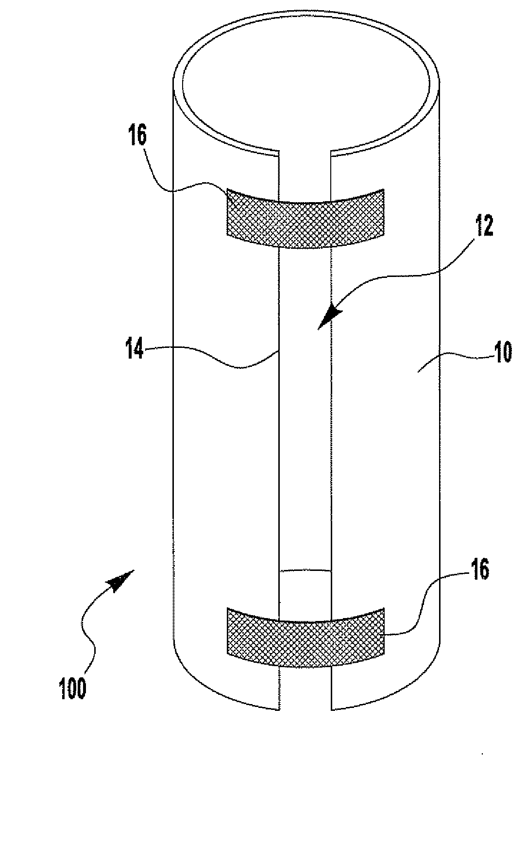
[0014]The present invention relates to a self-adjusting payoff core employed in a wire coil container, such as those employed in welding operations, to allow for low and consistent feed force during wire payout.

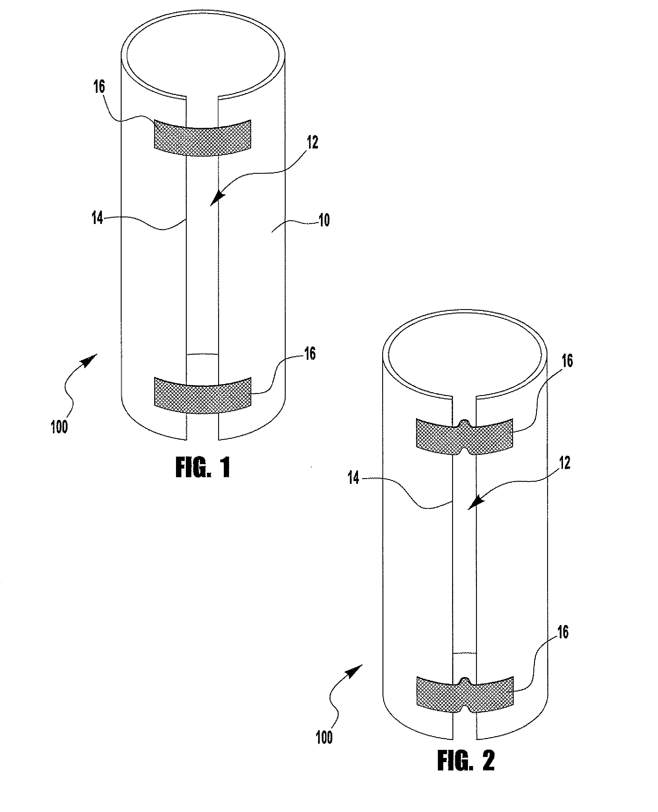
[0015]FIGS. 1 and 2 depict a self-adjusting payout core 100 according to an embodiment of the present invention. The core 100 contains a wall section 10 which is essentially cylindrical in shape having a slit section 12 running vertically along a length of the wall section 10. This slit section 12 creates a gap between edges 14 of the wall section 10 such that a diameter and thus cross-section of the core 100 is adjustable, as the gap 14 is reduced or enlarged.

[0016]Bridging the gap 14 are a plurality of straps 16 secured to the wall section 10. The straps 16 are made from a flexible material, allowing the wall section 10 to be deflected, thus enabling the gap 14 to be reduced. Further, the straps 16 are strong enough, and secured in such a fashion, so as to maintain a maximu...


PUM


Abstract

An invention is provided which employs a self-adjusting core section having an outer diameter which essentially matches that, or is larger than that, of the inner diameter of a wire coil, where the self-adjusting core has a vertical slit along the its length to allow the diameter of the core to be adjustable. Bridging the vertical slit are straps secured to the core to determine the core's maximum diameter, and allow the core diameter to be reduced through flexing.

Description

FIELD OF THE INVENTION[0001]The present invention is directed to self adjusting payoff core, more specifically to a self-adjusting payoff core used with wire coils employed in welding operations, and other similar applications.BACKGROUND OF THE INVENTION[0002]In some welding operations, such as MIG welding, a wire coil is employed to provide a continuous feed of welding wire (electrode) to the welding gun. In these applications, the welding wire is often stored in a large coil configuration, in which the coil of wire is placed in a box or a container having a core section around which the wire is coiled. The core section is employed to maintain coil stability as the wire is pulled out of the box during the welding operation.[0003]However, there are problems associated with this configuration. First, as the wire is pulled from the container the loop diameter of the wire becomes smaller (due to the pulling tension on the wire). Because of this, the wire falls between a gap between the...

Claims


Application Information

Patent Timeline
Patent Type & Authority Applications(United States)
IPC IPC(8): B65H75/24
CPCB65H75/24B65H75/10
Inventor FABIAN, GABOR
Owner LINCOLN GLOBAL INC
Why Eureka
Try Eureka