Remotely reconfigurable system for mapping subsurface geological anomalies

a remote reconfigurable system and geological anomaly technology, applied in the direction of reradiation, pulse technique, instruments, etc., can solve the problems of reducing the resistance to tensile forces and vibration, prone to cracking of slab-on-grade foundations, and extraordinary resistance to compressive forces of typical concrete, so as to achieve the effect of not requiring excessive downtim

Active Publication Date: 2008-06-12
EARTHSYST TEHNOLOGIES INC
View PDF22 Cites 15 Cited by
  • Summary
  • Abstract
  • Description
  • Claims
  • Application Information

AI Technical Summary

Benefits of technology

This patent describes how multiple sensors in an array can easily replace one another if there is any damage. Each sensor has its own unique code that allows it to communicate with a central controller. Even when replacing a damaged part, the new sensor will still have no problem identifying which position it belongs to within the overall system.

Problems solved by technology

The technical problem addressed in this patent is finding effective ways to detect and locate leaks from fluids contained in landfills, hazardous waste containers, and other types of structured facilities. Existing techniques have limitations including requiring permanent placement of electrodes, lack of flexibility in sensor configuration, and difficulty in switching between current locations. Additionally, previous methods require identifying encapsulated steel structures and mapping the location of electrodes based on surveys or grids. There is a need for improved remote monitoring technology that addresses these issues.

Method used


Image

  • Remotely reconfigurable system for mapping subsurface geological anomalies
  • Remotely reconfigurable system for mapping subsurface geological anomalies
  • Remotely reconfigurable system for mapping subsurface geological anomalies

Examples


Embodiment Construction

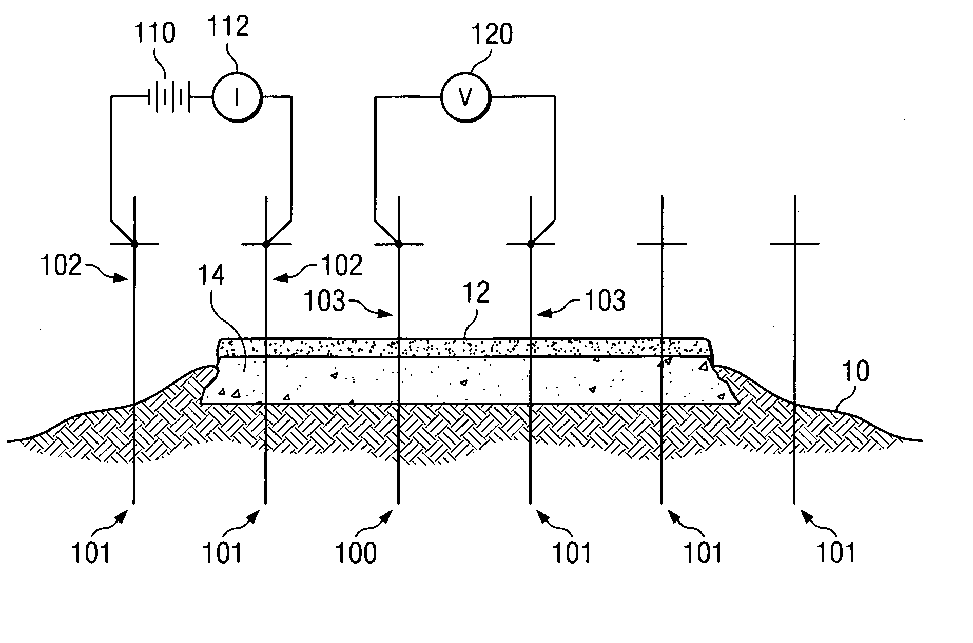
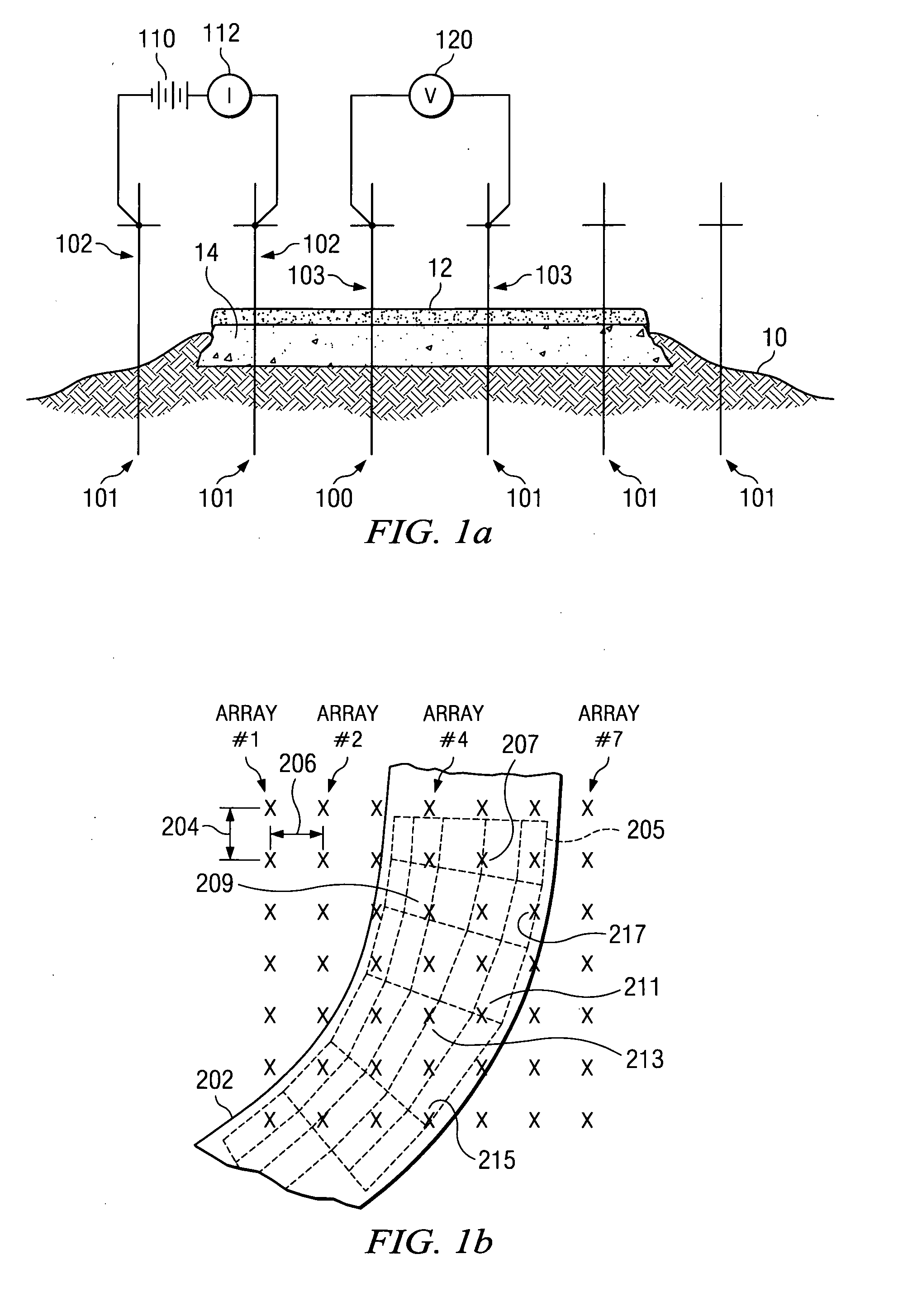
[0061]A schematic diagram of the theory used to gather data as used in the preferred embodiment is shown in FIG. 1a. A series of electrodes 101 are inserted, typically in a line, into ground 10. FIG. 1 shows the preferred embodiment as applied to an asphalt paved roadway. Asphalt layer 12 is applied on top of mid-level layer 14. Adhering to typical road construction principles, mid-level layer 14 may be a layer of concrete, steel reinforced concrete, or a compacted layer of gravel. In some situations, asphalt layer 12 may not be present. Electrodes 101 are inserted through both asphalt layer 12 and mid-level layer 14 and into ground 10 in order to determine resistivity and to map and detect subsurface soil anomalies under the roadway. The locations of electrodes 101 are typically in a regular pattern with a known interstitial distance between each electrode. In most situations, the known interstitial distance ranges from 6 to 10 feet and an equal interstitial distance is used betwee...


PUM


Abstract

A method and apparatus are provided for detecting and transmitting geophysical data from a plurality of electrodes inserted into the soil utilizing a set of identical dynamically reconfigurable voltage control units located on each electrode and connected together by a communications and power cable. A test sequence is provided in each voltage control unit. Each voltage control unit records data measurements for transmission to a central data collector. Each voltage control unit incorporates and determines its positional relationship to other voltage control units by logging when the unit is attached to the electrode. Each voltage control unit I equipped with a magnetic switch for detecting when they are in contact with the electrode.

Description


Claims


Application Information

Patent Timeline
Owner EARTHSYST TEHNOLOGIES INC
Why Eureka
Try Eureka