Backscatter transponder

Inactive Publication Date: 2008-06-12
ATMEL CORP
View PDF26 Cites 64 Cited by
  • Summary
  • Abstract
  • Description
  • Claims
  • Application Information

AI Technical Summary

Benefits of technology

[0017]It is therefore an object of the present invention to provide an improved a

Problems solved by technology

However, this method is extraordinarily expensive, since it is necessary to provide a transponder specifically intended for this purpose which has appropriate analysis and storage devices.
Since the passive and semipassive transponders that are customarily used do not have transponder-internal test devices for the sole purpose of testing, not least for reasons of cost, transponders so equipped would be complicated in terms of circuit design, and thus cost-intensive.
Furthermore, only a static test would be possible with this type of transponder test, since the data acquired could only be read out and analyzed

Method used


Image

  • Backscatter transponder
  • Backscatter transponder
  • Backscatter transponder

Examples


Embodiment Construction

[0054]In the drawings, like or functionally like elements and signals are identified with the same reference labels, unless otherwise specified.

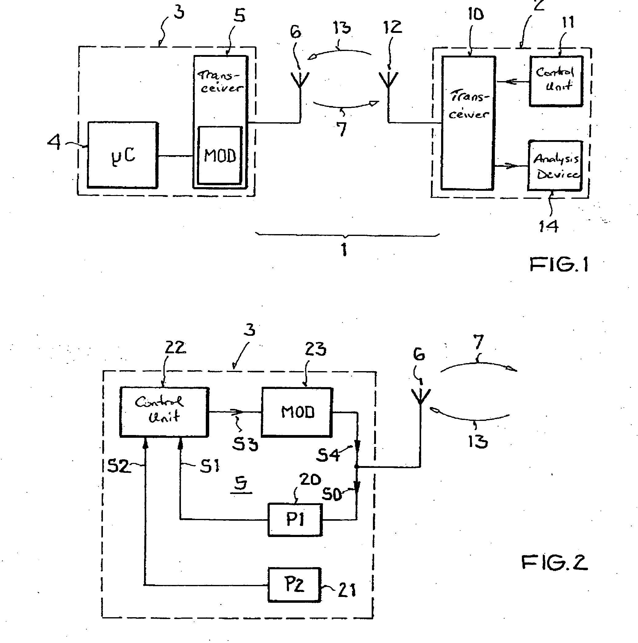
[0055]FIG. 1 uses a block diagram to show the conceptual structure of an RFID system with a base station and a transponder communicating with this base station.

[0056]The communication system labeled with reference symbol 1 has a base station 2 and a transponder 3, for example, a backscatter transponder. Base station 2 and transponder 3 are in communicative connection here. The communication system 1, which is an RFID system for example, can be designed as a so-called master / slave communication system in which the base station 2 functions as the master and the transponder or transponders 3 each function as slaves.

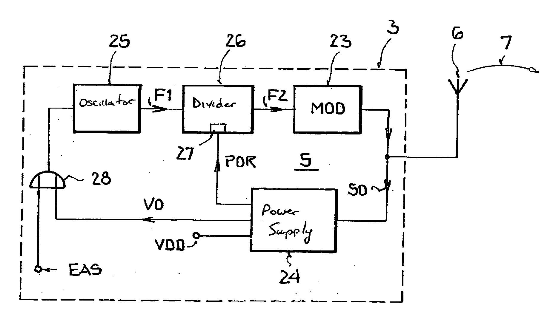
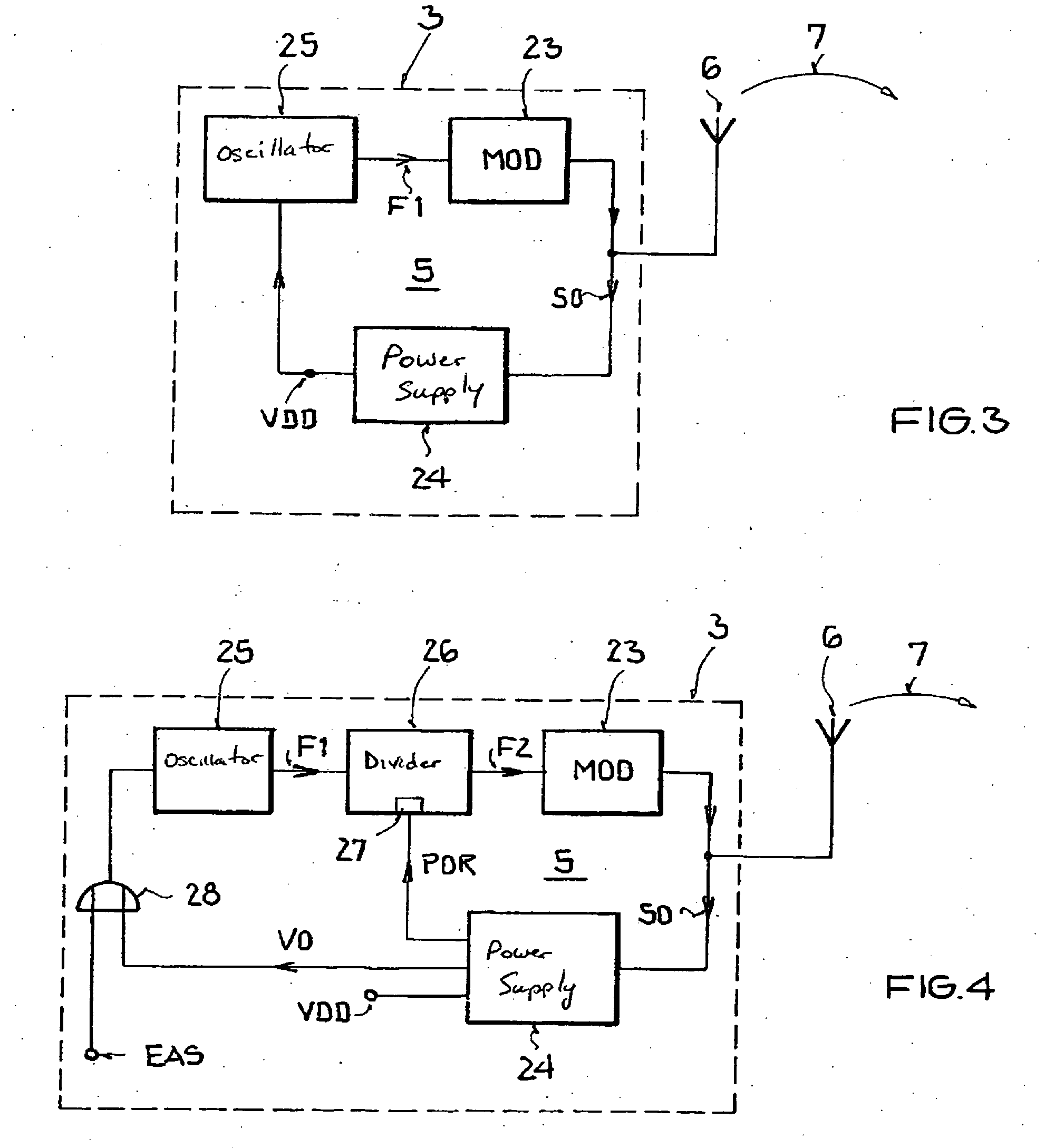
[0057]The transponder 3 includes a control unit 4, a transmitting / receiving device 5, and a transmitting / receiving antenna 6. The transmitting / receiving device 5, which is coupled to the control unit 4 and to the transmitting / receivi...


PUM


Abstract

A backscatter transponder for an HF communication system with modulated reradiation, is provided that includes an antenna for receiving high-frequency carrier signals, wherein the antenna has reflective characteristics, a control unit for providing transponder-specific parameters, and a modulator that can be driven by the control unit. The modulator altering the reflective characteristics of the antenna in accordance with at least one transponder-specific parameter.

Description

[0001]This nonprovisional application claims priority under 35 U.S.C. § 119(a) on Patent Application No. 10 2004 062 132.2 filed in Germany on Dec. 23, 2004, which is herein incorporated by reference.BACKGROUND OF THE INVENTION[0002]1. Field of the Invention[0003]The invention relates to a backscatter transponder for an HF communication system with modulated reradiation.[0004]The invention resides in the field of transponder technology and more particularly in the field of contactless communication for the purposes of identification. Although applicable in principle to any desired communication systems, the present invention and the problems it was designed to solve are explained below with respect to RFID communication systems and their applications. RFID stands for “Radio Frequency Identification.”[0005]2. Description of the Background Art[0006]In RFID systems, typically an electromagnetic signal sent out by a base station (reader) is received and demodulated by the transponder (t...

Claims


Application Information

Patent Timeline
IPC IPC(8): G08B13/14
CPCG06K7/0095G06K19/0723G06K19/0716
Inventor FRIEDRICH, ULRICH
Owner ATMEL CORP
Why Eureka
Try Eureka