
Liquid resistive touch panel

a touch panel and resistive technology, applied in the field of resistive touch panels, can solve the problems of affecting visual acuity, reflected light may create glare or otherwise, and the type of touch panel described above is associated with a number of undesirable limitations, and achieve the effect of superior optical properties

Inactive Publication Date: 2008-06-12
SONY ERICSSON MOBILE COMM AB
View PDF9 Cites 74 Cited by
  • Summary
  • Abstract
  • Description
  • Claims
  • Application Information

AI Technical Summary

Benefits of technology

[0009]Implementations of the present invention provide a resistive touch panel with superior optical properties.
[0025]Implementations of the invention may allow the provision of clearer images that exhibit superior contrast in high ambient lighting for an associated display. Other implementations may enable the removal of troublesome optical defects, such as Newton's rings. Still other implementations may obviate the need for spacers and other elements designed to counter optical distortions, such as diffusive anti-Newton's ring layers.

Problems solved by technology

Touch panels of the type described above are associated with a number of undesirable limitations.
The reflected light may create glare or otherwise impact visual acuity from the perspective of the user of the panel.
The reflected light may also render the panel a grayish color, thereby limiting the possibility to provide differentiated designs and / or colors of images presented via the panel.
Another limitation of such touch panels is that the flexible layer, after having been pressed towards the inner layer, may not completely return to its original position.
The indentation may produce so-called, Newton's rings, or similar optical distortions, which are undesirable from the perspective of the user of the panel.
However, the diffusive layer may also diffuse light emanating from a display provided below the touch panel, thereby reducing the sharpness of an image provided by the display.
An image to be presented, for example, in a relatively small portable electronic device may be reduced to an unacceptable degree of sharpness when subjected to the diffusive layer.
Limited resolution due to small dimensions of the touch panel in such devices places a premium on images being as sharp as possible.
This is not possible to do with the above mentioned diffusive layer.
However, the proposed composite will not, in all likelihood, improve the visibility of an underlying display due to the inclusion of the electrically conducting particles.

Method used


Image

  • Liquid resistive touch panel
  • Liquid resistive touch panel
  • Liquid resistive touch panel

Examples


Embodiment Construction

[0031]An electronic device according to an implementation of the present invention will now be described in relation to a mobile phone. The electronic device may be a portable communication device of some other type, like a cordless phone, a communication module, a PDA (personal digital assistant), or any other type of portable device, for example, for communicating via radio waves. In other implementation, the device may include a gaming machine, a notepad, or any other type of portable electronic device.

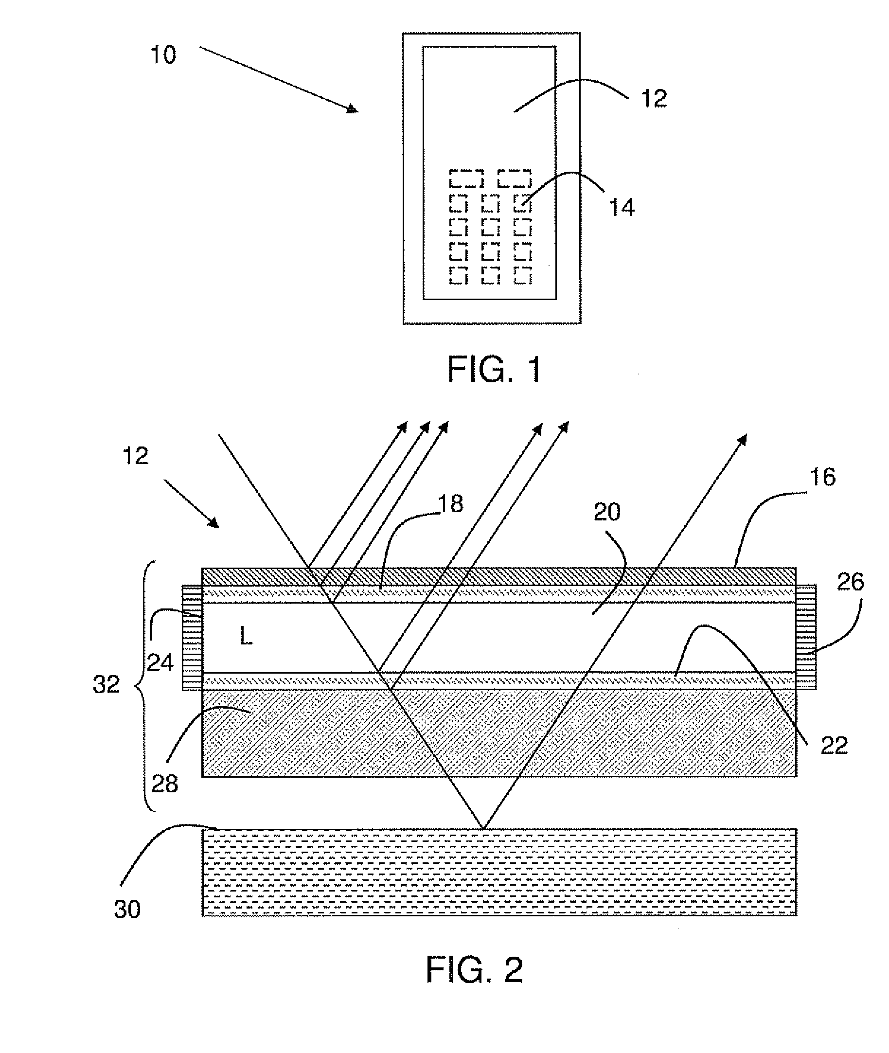
[0032]FIG. 1 schematically shows a front view of a phone according to one implementation. Phone 10 may include an information presenting device 12, which may include a touch panel provided over a display. The display may display information in the form of a keypad 14, and when the touch panel is touched in an area where a key is provided, information corresponding to the key may be registered by the touch panel and entered into phone 10.

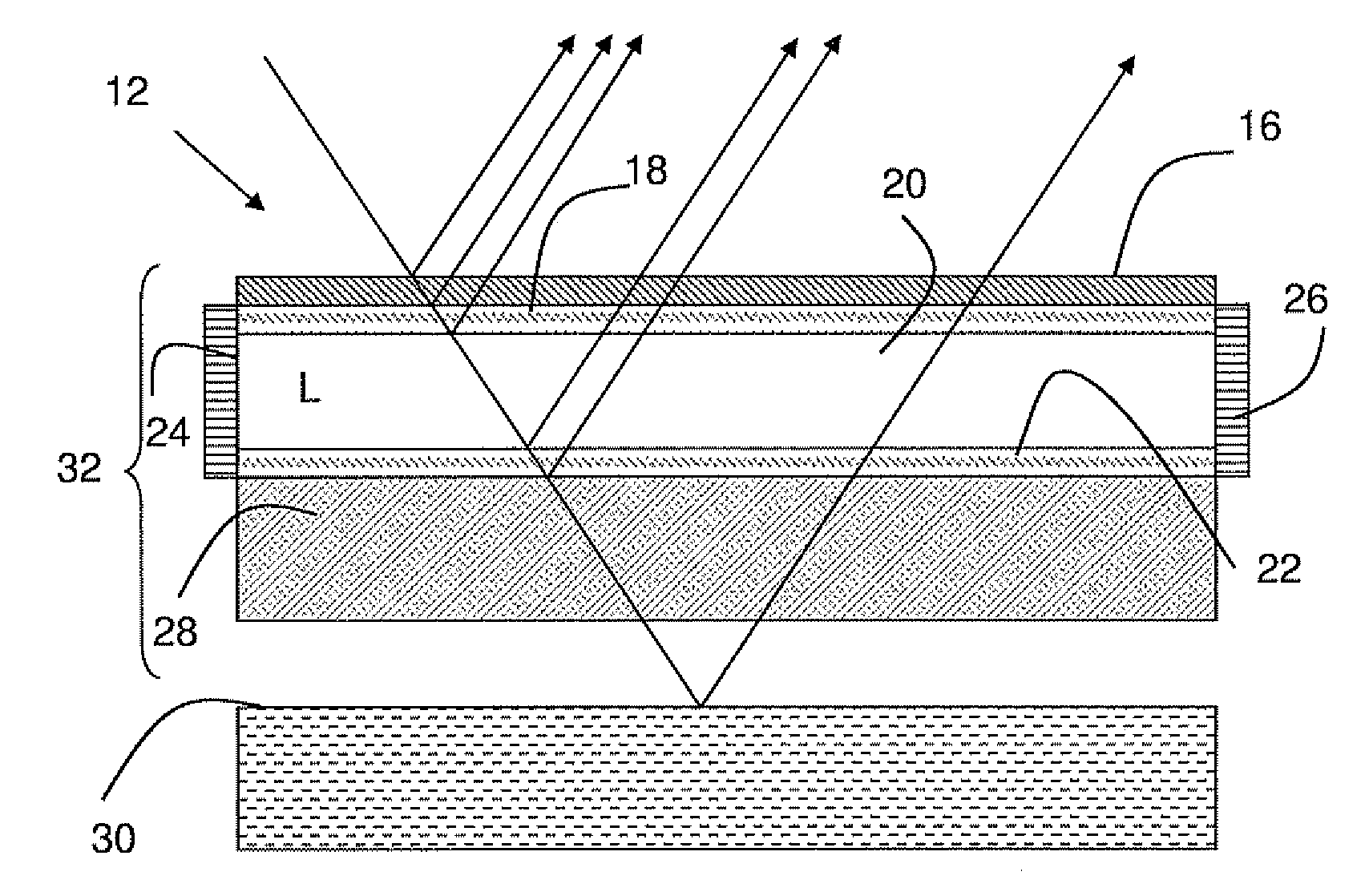
[0033]FIG. 2 schematically shows a side view ...


PUM


Abstract

A portable electronic device may include a resistive touch panel that may include an information presentation device. The resistive touch panel may include a flexible outer electrically conducting layer, an inner electrically conducting layer, and a separating chamber containing a liquid may be provided between the outer and inner electrically conducting layers.

Description

RELATED APPLICATIONS[0001]This application claims priority under 35 U.S.C. § 119 based on U.S. Provisional Application Ser. No. 60 / 868,979, filed Dec. 7, 2006, the disclosure of which is incorporated herein by reference.BACKGROUND[0002]The present invention generally relates to electronic devices and, more particularly, to a resistive touch panel, as well as an information presentation device and a portable electronic device including the resistive touch panel.[0003]In electronic devices such as portable communication devices, such as cellular phones, resistive touch panels are widely used as an input mechanism for receiving information from a user. Touch panels are often provided in conjunction with a display, such as an LCD (liquid crystal display). In such arrangements, the display may be used to render information associated with the information that is entered via the touch panel.[0004]A resistive touch panel is often multi-layered, and may include an outer electrically conduct...

Claims


Application Information

Patent Timeline
IPC IPC(8): G06F3/045
CPCG06F3/045
Inventor NISSAR, BENGT FREDRIK
Owner SONY ERICSSON MOBILE COMM AB
Learn More