Multi-mode exterior lighting architectures for aircraft

a multi-mode, aircraft technology, applied in the direction of lighting and heating apparatus, landing aids, lighting support devices, etc., can solve the problems of inefficiency of single-function architecture, inconvenient design of all the necessary lighting systems in small airplanes, and inconvenient design of aircraft lighting systems

Inactive Publication Date: 2008-06-12
THE BOEING CO
View PDF12 Cites 75 Cited by
  • Summary
  • Abstract
  • Description
  • Claims
  • Application Information

AI Technical Summary

Problems solved by technology

Present day airplane lighting system architectures, however, suffer from several drawbacks.
However, such single-function architecture is space and weight inefficient.
In addition, it is difficult to design all the necessary lighting systems into smaller airplanes.
Typically, light assemblies cannot be positioned on control surfaces, such as on the flaps of airplane wings.
In addition, light assemblies cannot be positioned where they will interfere with the laminar flow of air over the airplane's surfaces.
Vibration along with exposure to the elements and impact damage result in very low reliability of retractable lighting assemblies.
Further, designing the necessary lighting systems into small and large airplanes becomes difficult when new lighting technology is used.
However, HID light sources require special ballasts that are larger and heavier than the transformers used for conventional lamps.
In addition, larger HID sources typically start more slowly than incandescent / halogen sources, and many cannot be cycled on and off rapidly.
HID light sources are also susceptible to mechanical vibration and shock damage, burn position misalignment, excessive numbers of start cycles, and the like.

Method used


Image

  • Multi-mode exterior lighting architectures for aircraft
  • Multi-mode exterior lighting architectures for aircraft
  • Multi-mode exterior lighting architectures for aircraft

Examples


Embodiment Construction

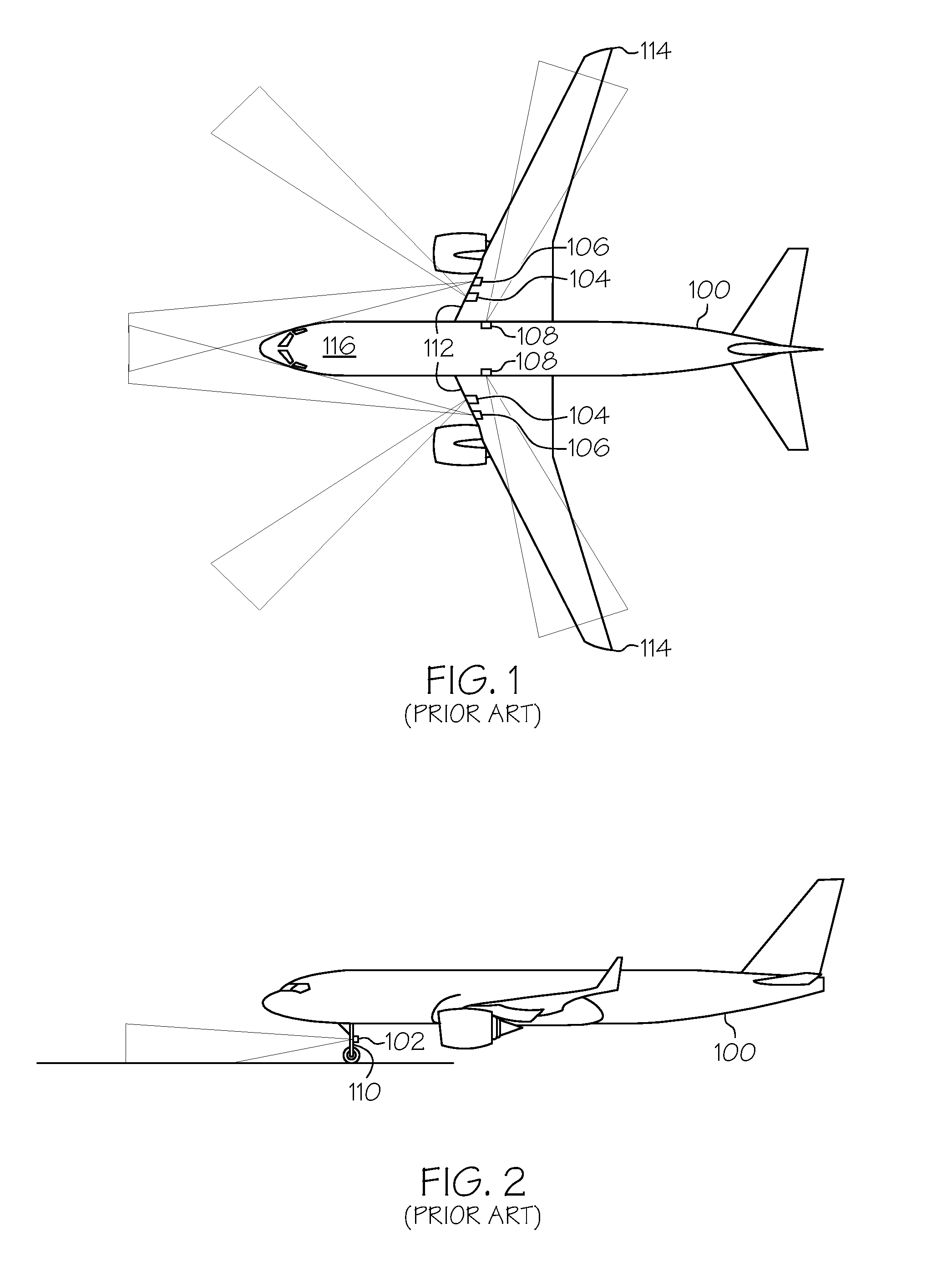
[0035]The following detailed description is merely exemplary in nature and is not intended to limit the described embodiments or the application and uses of the described embodiments. Furthermore, there is no intention to be bound by any expressed or implied theory presented in the preceding technical field, background, brief summary or the following detailed description. In addition, while the figures used herein may indicate a particular model or manufacturer of an airplane, it is understood that the various embodiments are not limited to a particular model or manufacturer and can be used for any suitable aircraft.

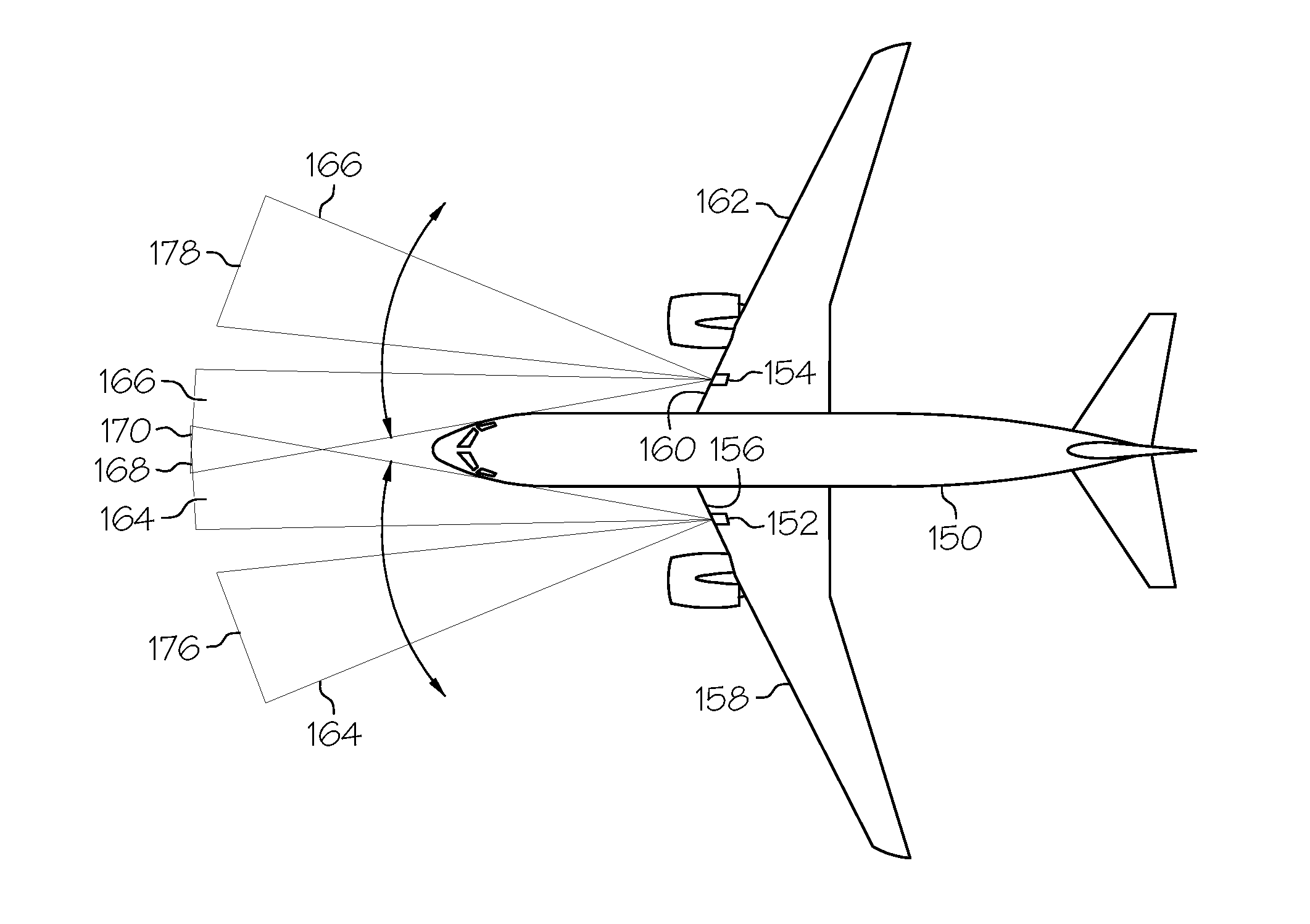
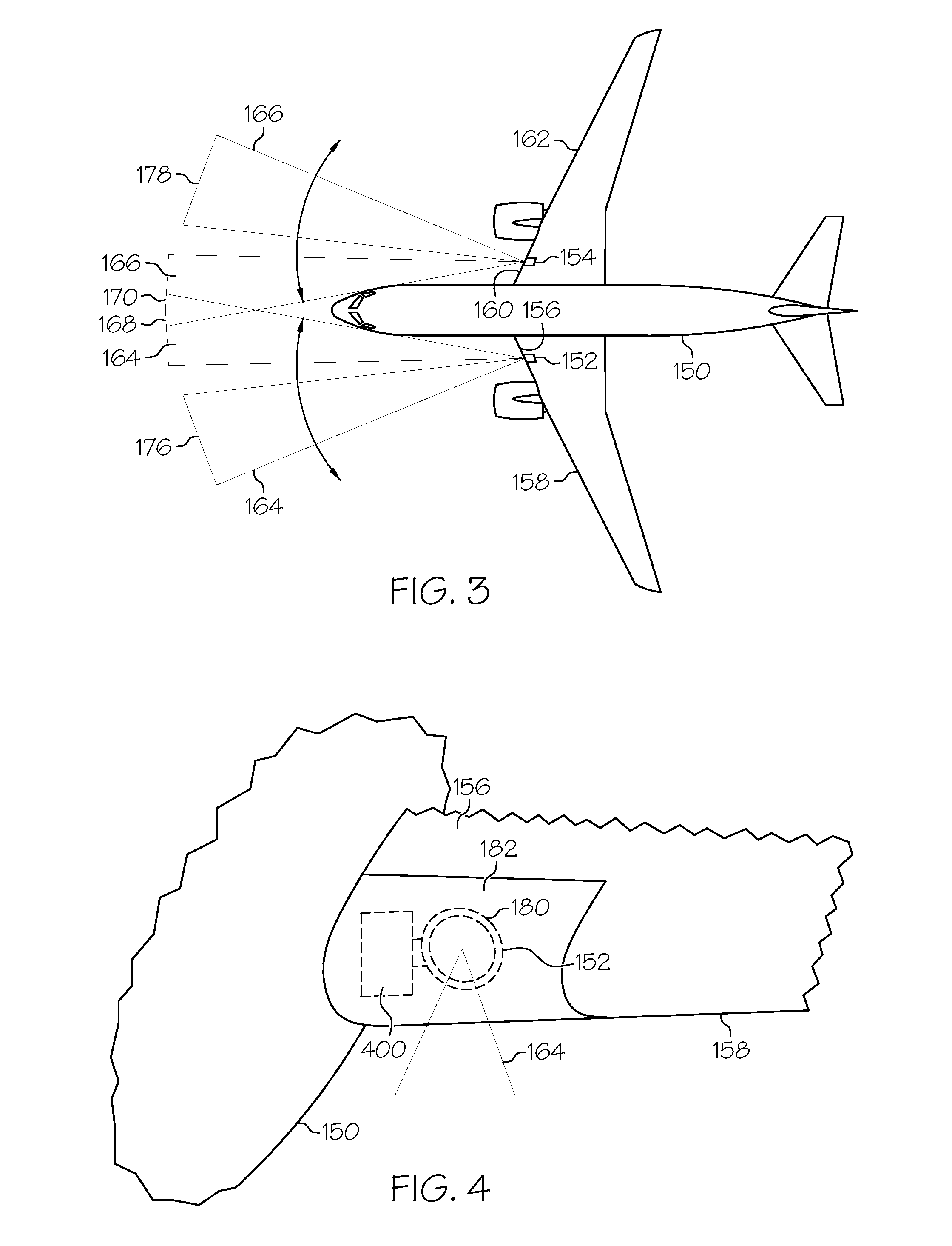
[0036]The various embodiments of the novel airplane lighting system architecture described herein utilize multi-function light assemblies to perform various functions depending on the operational mode of the airplane. This architecture is a more efficient design strategy than conventional architectures utilizing single-function light assemblies. The various embodiments o...


PUM


Abstract

Multi-mode exterior lighting architectures for aircraft are provided. In accordance with an exemplary embodiment, an illumination system for illuminating a plurality of positions exterior to an aircraft includes a first light assembly coupled to the aircraft. The first light assembly is configured to produce a first light beam and direct the first light beam at a first position during a first operational mode and at a second position during a second operational mode. A second light assembly also is coupled to the aircraft and is configured to produce a second light beam and direct the second light beam at a third position during the first operational mode and at a fourth position during the second operational mode.

Description

TECHNICAL FIELD[0001]The embodiments described herein generally relate to exterior lighting for aircraft, and more particularly relate to multi-mode exterior lighting architectures for airplanes.BACKGROUND[0002]Airplanes make use of multiple types and locations of high intensity exterior lighting systems for various operational modes. The lighting architecture used on an airplane depends on the size of the airplane, the space available for light assembly placement, and the type of light sources to be used. Light sources typically used for exterior applications on airplanes include high intensity discharge (HID), incandescent, halogen incandescent, light emitting diode (LED), and sealed beam parabolic aluminized reflector (or “PAR”) lamps of various sizes.[0003]Generally, at least one of three different types of lighting systems are used on airplanes. An example of a light architecture commonly used on airplanes is illustrated in FIGS. 1 and 2. Taxi light systems 102 are used on the ...

Claims


Application Information

Patent Timeline
Patent Type & Authority Applications(United States)
IPC IPC(8): B64D47/02B64F1/20
CPCB64D47/04
Inventor LARSEN, TY A.TRAN, LOC T.COTE, RICHARD A.
Owner THE BOEING CO
Why Eureka
Try Eureka