Battery module

a battery module and module technology, applied in the field of batteries, can solve the problems of decreasing the strength of the boundary portions, and achieve the effect of compact siz

Active Publication Date: 2008-06-12
ENVISION AESC JAPAN LTD
View PDF8 Cites 62 Cited by
  • Summary
  • Abstract
  • Description
  • Claims
  • Application Information

AI Technical Summary

Benefits of technology

[0008]Accordingly, one object of the present invention is to provide a battery module that is not readily affected by an input of vibration and can be made in a compact size

Problems solved by technology

Such concentrations of stress can cause fatigue at the boundary portions and cause the strength of the boundary portions to decline.

Method used


Image

  • Battery module
  • Battery module
  • Battery module

Examples


Embodiment Construction

[0041]Selected embodiment of the present invention will now be explained with reference to the drawings. It will be apparent to those skilled in the art from this disclosure that the following description of the embodiment of the present invention is provided for illustration only and not for the purpose of limiting the invention as defined by the appended claims and their equivalents.

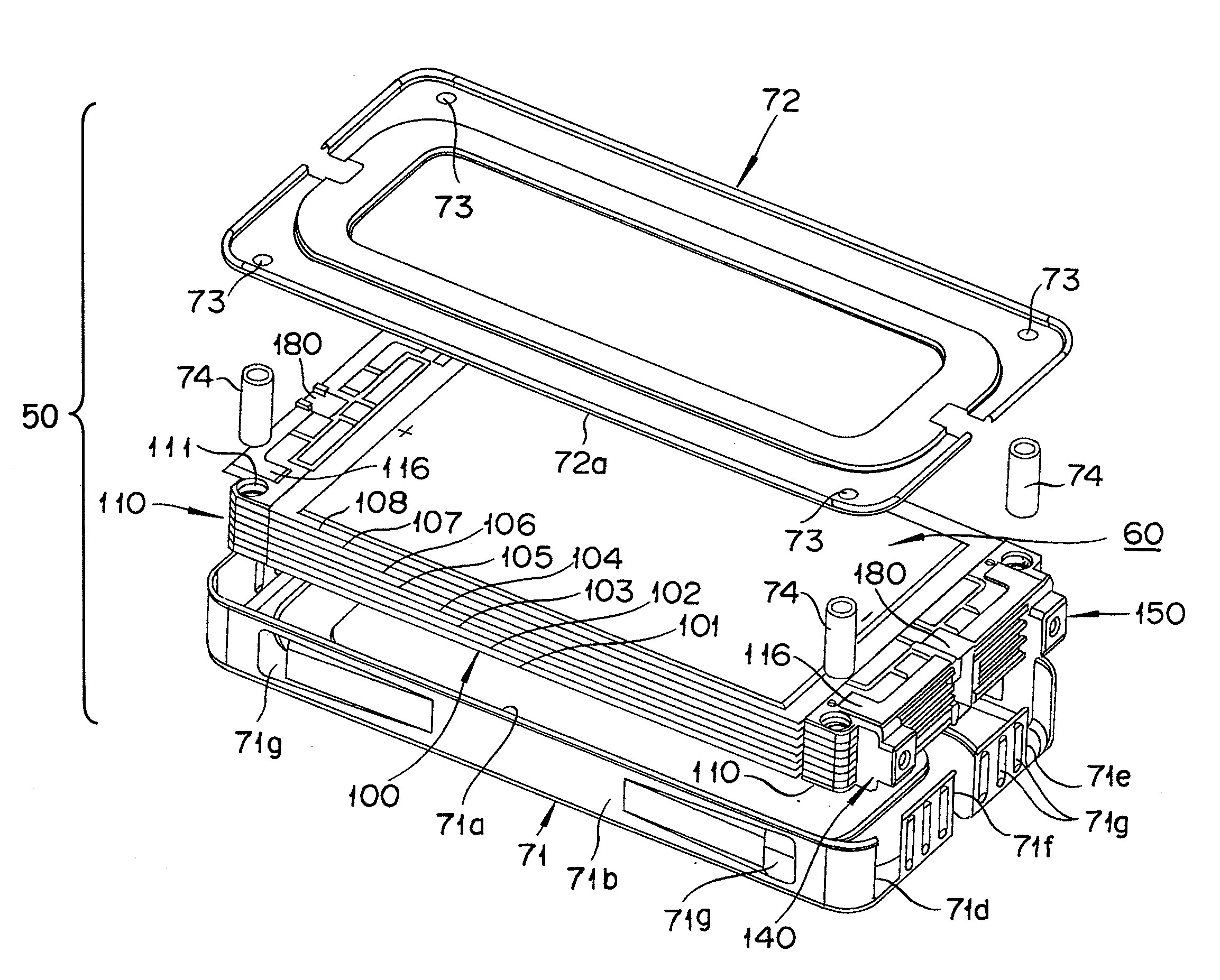
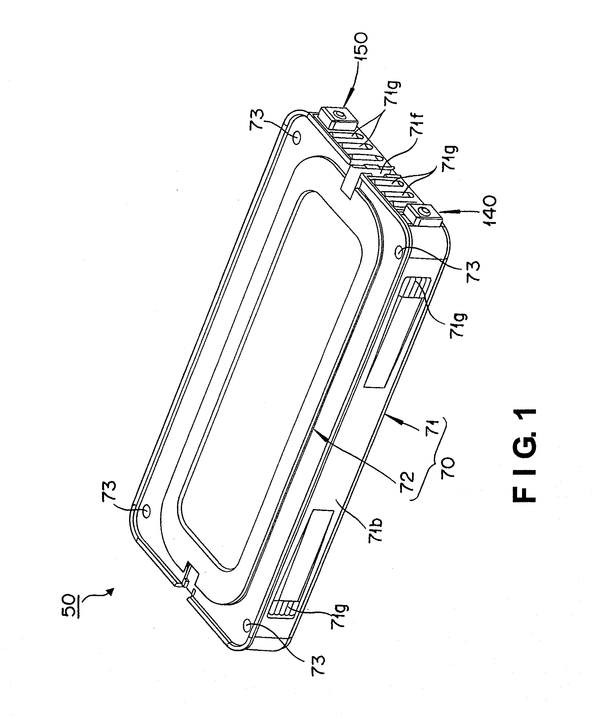
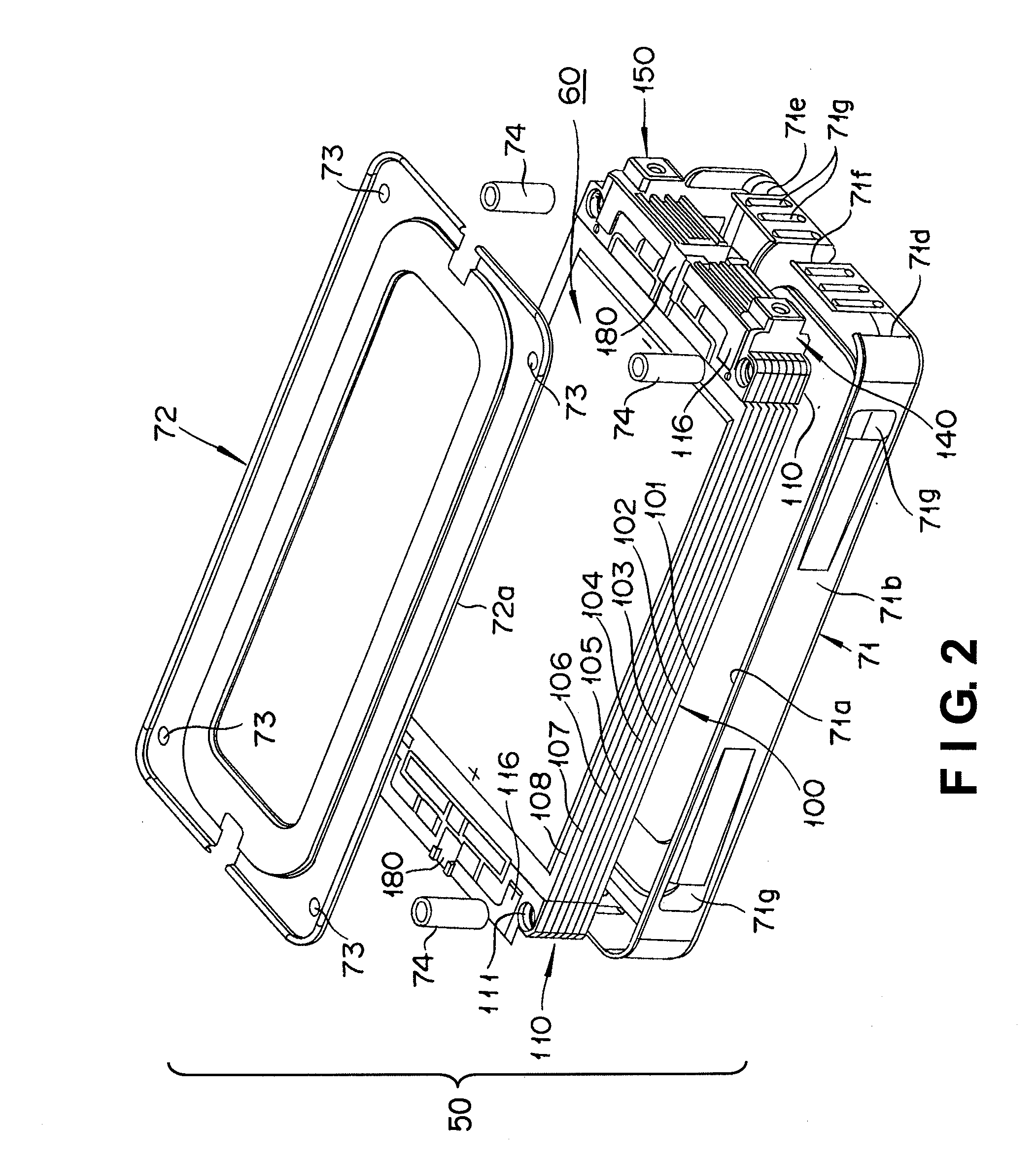
[0042]Referring initially to FIGS. 1 to 4, a battery module 50 is illustrated in accordance with one embodiment of the present invention. More specifically, FIG. 1 is an overall perspective view of the battery module 50 in accordance with an embodiment of the present invention. FIG. 2 is an exploded perspective view of the battery module 50 shown in FIG. 1. FIG. 3 is a perspective view of a cell unit 60 of the battery module 50 as it appears when removed from a case 70 in which the cell unit 60 is housed. FIG. 4 is a perspective view of a plurality of thin cells 101 to 108 (flat cells) that form the ce...


PUM

PropertyMeasurementUnit
electrically insulatingaaaaaaaaaa
areaaaaaaaaaaa
elasticaaaaaaaaaa

Abstract

A battery module includes a plurality of flat cells and a plurality of nipping plates. Each of the flat cells has a cell main body and at least one electrode tab. The cell main body includes a power storage element sealed in a package member. The electrode tab is electrically connected to the power generating member and protruding outwardly from the cell main body. The flat cells are stacked on one another such that the electrode tabs are electrically connected in a stacking direction. Adjacent ones of the nipping plates in the stacking direction nip the electrode tab and a portion of the cell main body of a corresponding one of the flat cells from both opposite side surfaces of the corresponding one of the flat cells along the stacking direction.

Description

CROSS-REFERENCE TO RELATED APPLICATIONS[0001]This application claims priority to Japanese Patent Application No. 2006-333693, filed on Dec. 11, 2006. The entire disclosure of Japanese Patent Application No. 2006-333693 is hereby incorporated herein by reference.BACKGROUND OF THE INVENTION[0002]1. Field of the Invention[0003]The present invention relates to a battery module that contains a plurality of thin cells stacked on one another in a thickness direction of the thin cells.[0004]2. Background Information[0005]There is a known technology for a thin battery (cell) comprising a cell main body that is made up of a power storage element sealed in a laminate film or other package member and a thin plate-shaped electrode that is electrically connected to the power storage element and configured to lead to an outside from the cell main body. Japanese Laid-Open Patent Application Publication No. 2001-256934 discloses a battery module case in which the thin batteries are stacked in the th...

Claims


Application Information

Patent Timeline
Patent Type & Authority Applications(United States)
IPC IPC(8): H01M10/48H01M10/36H01M50/105H01M50/211H01M50/264H01M50/528
CPCH01M2/0207H01M2/1061H01M6/46H01M2/1083H01M2/1077H01M50/105H01M50/264H01M50/211H01M50/50H01M50/528H01M50/10
Inventor OGAMI, ETSUOSHIRAISHI, NOBUHIROAMAGAI, RYUICHI
Owner ENVISION AESC JAPAN LTD
Why Eureka
Try Eureka