Systems and methods for powered tap assemblies

a technology of power supply and power supply, applied in the direction of electrical equipment, coupling contact members, connections, etc., can solve the problems of only being effective marketing tools, traditional decorative tap handles, and not providing electrical power, so as to maintain rotational independence, maintain integrity, and reduce the effect of breakage with consistent us

Inactive Publication Date: 2008-06-12
VOLTAP
View PDF5 Cites 6 Cited by
  • Summary
  • Abstract
  • Description
  • Claims
  • Application Information

AI Technical Summary

Benefits of technology

[0007]The present invention addresses drawbacks associated with prior powered tap assembly designs by providing systems and methods that allow for independent rotation of a particular tap assembly's conductive wire entry point as compared to the rest of the tap assembly while also allowing for the control of the wire's final orientation and protection of the wire at its entry point into the tap assembly and while also providing a design that maintains the integrity of the powered tap assembly by preventing dirt or other debris from entering relevant portions of the assembly through the wire's entry point. The present invention provides this benefit by providing a slip ring with a conductive wire entry point between each tap assembly's locknut and ferrule assembly. The slip rings according to the present invention can rotate independently as compared to the other components of the tap assembly. Further, the slip rings provide a novel way for electrical power to enter into a tap handle. Specifically, the slip ring acts to control the direction of the wire as it enters into the tap assembly. Further, the slip ring design advantageously provides a connection which is protected and subjected to much less fraying and breakage than previously designed powered tap handle systems. The slip ring also provides a reliable mechanism for maintaining rotational independence that is less likely to break down with consistent use. In addition, the ferule assembly of the present invention provides a reliable mechanism for attaching a tap handle to a powered tap assembly. The present invention also provides for a tap assembly that is sleeker and more attractive than previous systems, which is important given the use of tap handles for advertising.

Problems solved by technology

However, traditional decorative tap handles, which are commonly made of plastic or wood, have certain limitations.
Specifically, and as currently used, these traditional handles are not provided with electrical power.
By lacking electrical power, the traditional tap handles can only be effective marketing tools if the potential customer is already looking at the tap, as the non-powered handles are unable to draw attention in the way that an electrically-powered lighted, sound producing or moving tap handle could.
While the design described in the '638 patent provided a number of important advances, certain drawbacks that made the mounting and use of the described beer tap assemblies more difficult than necessary in some circumstances remained.
This configuration generated a number of unanticipated drawbacks.
For example, the orientation of the wire, when it exited the hole in the bushing, could not be controlled.
This lack of control had the dual results of limiting the possible configurations of the tap assembly and being aesthetically unpleasing (potentially resulting in the loss of advertising effectiveness).
Further, the wire was unprotected as it entered the hole, which often resulted in fraying or breakage.
In addition, the wire would get pinched between the bushing and the locknut, which also resulted in frequent fraying and breakage.
Moreover, the hole in the bushing allowed particles to enter into the cavity between the bushing and the locknut, which often resulted in the bushing losing its rotational independence, as well as adding yet another source of wear on the wire.
As a final example of drawbacks associated with the systems described in the '638 patent, these systems failed to provide for a reliable mechanism for attaching the bushing to the locknut.
This lack of reliable attachment resulted in the bushing frequently falling off of the locknut, thus crippling both the effectiveness and aesthetic appeal of the '638 system.

Method used


Image

  • Systems and methods for powered tap assemblies
  • Systems and methods for powered tap assemblies
  • Systems and methods for powered tap assemblies

Examples


Embodiment Construction

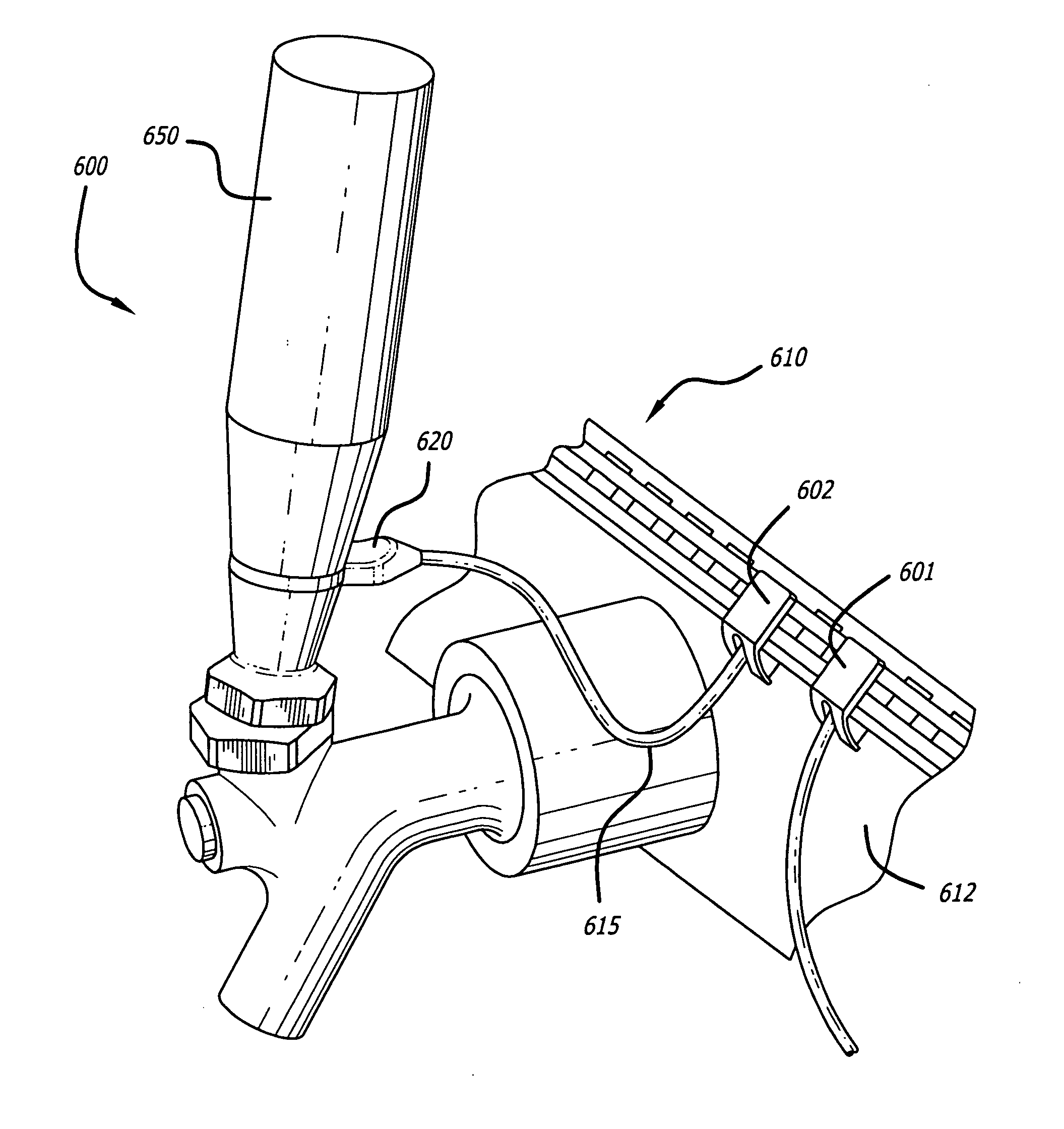
[0029]Existing tap handles as they are presently used in commercial establishments fail to capitalize on their full advertising potential by failing to effectively draw attention to the beverage with which they are associated. While this drawback was addressed in U.S. Pat. No. 6,932,638 (the '638 patent), which is fully incorporated by reference herein, the systems and methods described in the '638 patent had certain design features that could make their mounting and use more difficult than necessary in some circumstances. For example, due to a problematic wire entry position, those systems and methods had limited configurations. The previous mechanism for wire entry also often resulted in the wire fraying and breakage, thus crippling the functionality of the systems. Further, the '638 system was problematic in that it could not maintain the rotational independence of the wire entry point over a sustained period of time. The present invention addresses these drawbacks of previous ap...


PUM


Abstract

The present invention relates to systems and methods for providing electrical power to a tap handle on a beverage dispenser. Specifically, the present invention may be used to provide electrical power to beer tap handles.

Description

CROSS REFERENCE TO RELATED APPLICATIONS[0001]This application claims the benefit under 35 U.S.C. §119, of provisional U.S. application Ser. No. [Unassigned], filed Dec.11, 2006, the entire contents and substance of which is hereby incorporated by reference.FIELD OF THE INVENTION[0002]The present invention relates to systems and methods for providing electrical power to a tap assembly on a beverage dispenser.BACKGROUND OF THE INVENTION[0003]Bar taps are well known, and are traditionally used in conjunction with a beverage dispenser to control the release of the beverage. Normally, the beverage dispenser will have one or more tap stems, to which a decorative tap handle may be attached. Decorative tap handles are designed and used to let customers know that a certain beverage is available and to entice them to try that beverage.[0004]Specifically and in one non-limiting example, beer breweries create tap handles of all shapes and sizes to brand their product, to lure new customers to t...

Claims


Application Information

Patent Timeline
Patent Type & Authority Applications(United States)
IPC IPC(8): H01R4/30
CPCH01R4/48H01R35/04H01R13/26
Inventor WILLIAMSON, CORY R.ALBINI, MARTINWERNIKOWSKI, THOMAS J.BURROWS, CHRISTIAN P.GENTZEN, MARKFICHTER, PAUL DANIEL
Owner VOLTAP
Why Eureka
Try Eureka